Table of Contents
Advertisement
Available languages
Available languages
BD850
Opening your life
Code:
MANUAL DE USUARIO
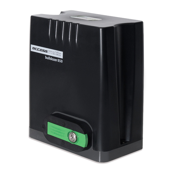
Motor para puerta corrediza
Bulldozer
850
ADVERTENCIA
Por favor lea el manual detenidamente antes de la instalación el uso del producto. La instalación de su
nueva puerta debe ser realizada por una persona técnicamente calificada o licenciada. Tratar de instalar o
reparar el motor sin tener la calificación técnica puede resultar en severas lesiones personales, muerte y/o
daños a la propiedad.
www.accessmatic.com
Opening your life
Advertisement
Chapters
Table of Contents

Related Manuals for Accessmatic Bulldozer 850


Summary of Contents for Accessmatic Bulldozer 850
- Page 1 Tratar de instalar o reparar el motor sin tener la calificación técnica puede resultar en severas lesiones personales, muerte y/o daños a la propiedad. www.accessmatic.com Opening your life...
-
Page 2: Table Of Contents
Opening your life Code: CONTENIDO Instrucciones de seguridad Lista de partes (estándar) Parámetros técnicos Instalación Procedimientos de instalación Cableado de la placa de control Ajuste de función Conexión por infrarrojos Operación de control remoto Solución de problemas Garantía www.accessmatic.com Opening your life... -
Page 3: Instrucciones De Seguridad
Lea este manual detenidamente antes de instalarlo, usarlo, mantenerlo o repararlo. Sin seguir este manual, cualquier lesión o pérdida de propiedad causada por un uso inadecuado o una modi cación no autorizada queda fuera de la responsabili- dad de nuestra empresa. www.accessmatic.com Opening your life... -
Page 4: Lista De Partes (Estándar)
Opening your life Code: Lista de partes (estándar) Imagen Nombre Cantidad Motor principal Llave manual Control remoto Caja de accesorios para limite de carrera mecanico Bloque de nal de carrera tornillo de montaje M6X18 Perno de cimentación M8 www.accessmatic.com Opening your life... - Page 5 BD850 Opening your life Code: Tuerca M8 Arandela plana Ø8 Arandela de resorte Ø8 www.accessmatic.com Opening your life...
-
Page 6: Parámetros Técnicos
/ Modo de tres botones Límite de cambio Final de carrera mecánico Ruido ≤56dB Trabajo pesado S2, 20min Guardar de mandos a distancia 433.92 MHz Frecuencia Temperatura de trabajo -20°C ~ +70°C 10.10kg Peso del paquete www.accessmatic.com Opening your life... -
Page 7: Instalación
③ 5) Lámpara de alarma (opcional) 6) Bloqueo de parada de seguridad 7) Cremallera 8) Control remoto ② ⑥ ⑦ ⑧ ① Figura 1 Tamaño del motor principal y accesorios Tamaño del motor principal Figura 2 www.accessmatic.com Opening your life... -
Page 8: Procedimientos De Instalación
BD850. Asegúrese de que la distancia entre la puerta y el abridor de la puerta sea la adecuada antes de colocar el pedestal. Tornillos empotrados Placa de montaje Tornillo de cementación Concreto Linea eléctrica Figura 4 www.accessmatic.com Opening your life... - Page 9 4) Suelde rmemente todos los tornillos de montaje a la puerta. 5) Asegúrese de que todas las rejillas estén en la misma línea recta. 6) Tire de la puerta después de instalarla, asegúrese de que todo el viaje sea exible sin ningún atasco. Figura 5 www.accessmatic.com Opening your life...
- Page 10 5) Después de la instalación, compruebe si la propiedad mecánica es buena o no, si el movimiento de la puerta después del desbloqueo manual es exible o no, si la instalación del sensor de infrarrojos (opcional) es correcta y e caz. www.accessmatic.com Opening your life...
- Page 11 Bloque de parada de nal de carrera mecánico Mecanismo de engranaje Engranaje de salida Figura 7 La instalación del bloque de parada del nal de carrera de muelle se muestra en la gura 8: M6×10 M6×10 M6×10 M6×10 Figura 8 www.accessmatic.com Opening your life...
- Page 12 Terminal J1 Conecte L & N al suministro de energía AC110V/60Hz; L is la línea viva, N es neutro, y PE es el polo a tierra. Terminal J2 Conecte LAMP a la lampara de precaución; Voltaje: AC110V/60Hz. www.accessmatic.com Opening your life...
- Page 13 PAUSA: Este botón se usa para de nir el tiempo de cierre automático. Cuando el motor esté detenido, oprima el botón y después el LED STS parpadear. Puede oprimir el botón nuevamente para que no siga parpadeando. El tiempo de cierre automático (segundos) depende de cuantas veces parpadee el LED STS. www.accessmatic.com Opening your life...
- Page 14 2 metros, de lo contrario afectará la inducción de la fotocelda. La siguiente gura muestra la conexión NO. Si quiere conectar a un infrarrojo NC, solo se debe cambiar al puerto NC. Después de realizar el cambio nuevamente haga el recorrido de aprendizaje. FIG 2 www.accessmatic.com Opening your life...
-
Page 15: Operación De Control Remoto
MOT2 y MOT1. Si los límites de nal de carrera en apertura o cierre están mal, puede cambiar los cables de los nales de carrera que se encuentran conectados a los termina- les LSC y LSO en la tarjeta de control. www.accessmatic.com Opening your life... - Page 16 En aras de la seguridad, se sugiere que cada puerta esté equipada con un protector de infrarrojos y se requiere una inspec- ción periódica. Antes de instalar y operar el abridor de puerta, lea atentamente todas las instrucciones. www.accessmatic.com Opening your life...
-
Page 17: Solución De Problemas
2) La puerta se encuentra con un obstáculo La puerta se abre automáticamente Consulte las atenciones en 4.3.5 para cambiar la dirección Se ha activado la función de cierre de apertura automático pero con dirección de apertura incorrecta www.accessmatic.com Opening your life... - Page 18 Parte eléctrica Si el motorreductor del equipo adquirido por el cliente, En la línea accessmatic la garantía de 3 años abarca presenta algún daño por defectos de fabrica o desajuste tarjetas y partes eléctricas, El (CSS) / (CSA) se compro- interno detectado a la hora de instalar el equipo.
-
Page 19: Garantía
BD850 Opening your life Code: Garantía para repuestos y accesorios Tipo de repuesto Sin instalación Especialista Accessmatic Certi cado (instalador) 30 días 180 días Tarjetas electrónicas internas. Motores internos. 30 días 180 días Baterías de respaldo, lámparas 180 días Centrales, fotoceldas, receptoras 1 año... - Page 20 Code: Consideraciones especiales 1. Los mantenimientos o visitas que ofrece Accessmatic en instalaciones no incluyen los viáticos requeridos para llegar al sitio donde se encuentra operando el equipo. Dichos viáticos deberán ser asumidos por el cliente. 2. Cualquier mantenimiento deberá ser realizado por personal autorizado (CSS) / (CSA) por lo cual es necesario que el cliente instale el producto con instaladores o distribuidores autorizados, de no ser así...
- Page 21 Please read the manual carefully before installation using the product. The installation of your new door must be carried out by a technically quali ed or licensed person. Attempting to install or repair the motor without technical quali cation can result in severe personal injury, death, and / or property damage. www.accessmatic.com Opening your life...
- Page 22 BD850 Opening your life Code: CONTENT Safety Instruction Packing List (standard) Technical parameters Installation Installation procedures Control board wiring Function adjustment Infrared connection Remote control operation Troubleshooting Warranty www.accessmatic.com Opening your life...
-
Page 23: Safety Instruction
Please read this manual carefully before installing、 using、 maintaining or repairing it. Without following this manual, any injury or property losses caused by improper use or unauthorized modi cation is out of the responsibility of our company. www.accessmatic.com Opening your life... -
Page 24: Packing List (Standard)
BD850 Opening your life Code: Packing List (standard) Picture Name Quantity Main engine Manual release key Remote control Spring limit switch accessories box Limit switch block mounting screw M6X18 Foundation bolt M8 www.accessmatic.com Opening your life... - Page 25 BD850 Opening your life Code: Nut M8 Flat washer Ø8 Spring washer Ø8 www.accessmatic.com Opening your life...
-
Page 26: Technical Parameters
Single button mode Remote control mode / Three button mode Limit switch Spring limit switch ≤56dB Noise Working duty S2, 20min Recording of up remote controls Frequency 433.92 MHz -20°C ~ +70°C Working temperature Package weight 10.10kg www.accessmatic.com Opening your life... -
Page 27: Installation
4) Infrared sensor (optional) 5) Alarm lamp (optional) 6) Safety stop block 7) Gear rack ② ⑥ 8) Remote control ⑦ ⑧ ① Figure 1 Size of main engine and acces- sories Size of main engine Figure 2 www.accessmatic.com Opening your life... -
Page 28: Installation Procedures
Please precast a concrete pedestal with the size can be 400mm x 250mm, depth be 200mm in advance, so as to rmly install BD850 gate opener. Please make sure the distance between the gate and gate opener is appropriate before casting the pedestal. Embedded screws Mounting plate Foundation bolt Concrete Power line Figure 4 www.accessmatic.com Opening your life... - Page 29 4) Weld all the mounting screws to the gate rmly. 5) Make sure that all racks on the same straight line. 6) Pull the gate after installed, make sure the entire trip is exible without any stuck. Figure 5 www.accessmatic.com Opening your life...
- Page 30 1.5m to avoid being touched by children. 5) After installation, please check whether the mechanical property is good or not, whether gate movement after manual unlocking is exible or not, whether the installation for infrared sensor (optional) is correct and e ective. www.accessmatic.com Opening your life...
- Page 31 Magnetic limit switch - The installation position of magnetic limit switch is shown in Figure 7: Gate Spring limit switch Gear rack Output gear Figure 7 The installation of spring limit switch stop block is shown in Figure 8: M6×10 M6×10 M6×10 M6×10 Figure 8 www.accessmatic.com Opening your life...
-
Page 32: Control Board Wiring
Wiring instruction: J1 Terminal Connect L and N to the power supply of AC110V/60Hz; L is live wire, N is Neutral wire, and PE is grounding wire. J2 Terminal Connect LAMP to caution light; voltage: AC110V/60Hz. www.accessmatic.com Opening your life... - Page 33 PAUSE: This button is used to set the automatic closing time .When the motor is not running, press the button and then led STS ashes. You can press the button again to stop ashing. The automatic closing time (seconds) depends on how many times the led STS ashes. START: This button is equal to J4 TERMINAL’s START port. www.accessmatic.com Opening your life...
-
Page 34: Infrared Connection
The following gure shows the NO infrared connection. If you want to connect to an NC infrared photo, just change to NC port. Then please learn travel again to Memory the infrared NC connection. FIG 2 www.accessmatic.com Opening your life... -
Page 35: Remote Control Operation
If the gate opening direction is wrong, you can toggle switch MOT.DIRECTION or exchange the motor phase-sequence lines MOT2 and MOT1. If the opening or closing limit is wrong, please exchange limit switch lines which are connected to the corresponding terminal LSC and LSO on the control board. www.accessmatic.com Opening your life... - Page 36 Check whether the gate operates normally every month. For the sake of safety, each gate is suggested to be equipped with infrared protector, and regular inspection is required. Before installation and operation of the gate opener, please read all instructions carefully. www.accessmatic.com Opening your life...
-
Page 37: Troubleshooting
2) Adjust the VR3 2) Gate meets obstacle 3) Remove the obstacle Gate opens automatically Please refer to the attentions under 4.3.5 to change the Automatic close function has been opening direction turned on but with incorrect opening direction www.accessmatic.com Opening your life... -
Page 38: Warranty
Geared motors Electrical part If the gearmotor of the equipment purchased by the In the accessmatic line, the 3-year warranty covers customer shows any damage due to manufacturing boards and electrical parts. The (CSS) / (CSA) under- defects or internal mismatch detected when installing takes to replace or repair any part that fails due to the equipment. - Page 39 BD850 Opening your life Code: Warranty for spare parts and accessories Spare type no installation Certi ed Accessmatic Specialist (Installer) 30 days 180 days Internal electronic boards. Internal motors. 30 days 180 days Backup batteries, lamps. 180 days Centrals, photocells, receivers...
- Page 40 Code: Special considerations 1. The maintenance or visits o ered by Accessmatic in facilities do not include the travel expenses required to reach the site where the equipment is operating. These travel expenses must be assumed by the end user.
- Page 41 Opening your life Opening your life Opening your life www.accessmatic.com www.accessmatic.com www.accessmatic.com...
Need help?
Do you have a question about the Bulldozer 850 and is the answer not in the manual?
Questions and answers