Table of Contents
Advertisement
Quick Links
Instructions-Parts
Advanced Web Interface Kit
Installation and setup instructions to allow communication between a PC and various Graco devices, via
an ethernet. For professional use only. Not for use in explosive atmospheres or hazardous locations.
Important Safety Instructions
Read all warnings and instructions in this manual and in your system
manual. Save these instructions.
Kit 15V337, Advanced Web Interface
(AWI)
Kit 15V336, AWI Server Hub
PROVEN QUALITY. LEADING TECHNOLOGY.
Get other manuals https://www.bkmanuals.com
332459A
EN
Advertisement
Table of Contents

Subscribe to Our Youtube Channel
Related Manuals for Graco 15V337

Summary of Contents for Graco 15V337
- Page 1 Instructions-Parts 332459A Advanced Web Interface Kit Installation and setup instructions to allow communication between a PC and various Graco devices, via an ethernet. For professional use only. Not for use in explosive atmospheres or hazardous locations. Important Safety Instructions Read all warnings and instructions in this manual and in your system manual.
- Page 2 Warnings The following warnings are for the setup, use, grounding, maintenance and repair of this equipment. The exclamation point symbol alerts you to a general warning and the hazard symbol refers to procedure-specific risks. When these symbols appear in the body of this manual or on warning labels, refer back to these Warnings.
- Page 3 Warnings WARNING EQUIPMENT MISUSE HAZARD Misuse can cause death or serious injury. • Do not operate the unit when fatigued or under the influence of drugs or alcohol. • Do not exceed the maximum working pressure or temperature rating of the lowest rated system component.
-
Page 4: Related Manuals
Related Manuals Related Manuals Manual Description Use For 313386 ProMix 2KS/3KS Web Interfaces All Installation, Setup, and Operation information for ProMix 2KS and ProMix 3KS AWI or Basic Web Interface. Manual 332459 is not needed for the ProMix family. 3A2040 Informer Instructions/Parts Follow all instructions in 332459 first, then see Appendix B for specific Informer Settings and Operation... -
Page 5: Installation
(the Informer, for example, or the ProControl 1KE). ProMix 2KS and ProMix 3KS Users: Please refer to Manual 313386. The Advanced Web Interface (AWI) is an accessory that works with many Graco devices and gateways. The AWI allows communication with a personal computer (PC) over an ethernet. With the AWI, users can view and change system setup parameters and create reports from a remote PC. - Page 6 2. Connect the AWI to another Graco device or gateway and to a PC. a. Shut off power to the Graco device (D). Also • To avoid electric shock, turn off power before shut off power at main circuit breaker.
-
Page 7: Installation Example
Installation Installation Example This sample installation is only a guide for setting up system communication. Contact your Graco distributor for assistance in planning a system to suit your needs. 332459A Get other manuals https://www.bkmanuals.com... -
Page 8: Computer Configuration
Computer Configuration Computer Configuration Set Up an Automatic IP Address e. Right-click Local Area Connection, then click Properties. The AWI requires an IP address obtained by your On the Local Area Connection Properties computer. Set up your computer to obtain one window, click Internet Protocol Version 4 automatically. - Page 9 Computer Configuration Set Up IP Address Manually If the automatic configuration does not work or cannot 3. Then, select Use the Following DNS Server be used with your system, the IP address required by Addresses. Fill in this address. the AWI can be set up manually. 192.168.178.200 1.
-
Page 10: System Initialization
Computer Configuration System Initialization NOTE: System initialization must be done by an 6. Initialization is complete. Click Finish. administrator. This process is required only when the system is first started. NOTE: Do not connect the system to a LAN unless it is configured properly first. -
Page 11: Password Recovery
Computer Configuration Password Recovery 1. If you type in the wrong password, sign in will be 3. Type the answer to your secret question, then click Next. blocked. Click on the block icon to initiate the password recovery sequence. 4. If the answer matches the one entered in Step 5, the system will prompt you for a new password. -
Page 12: System Configuration
System Configuration System Configuration Settings Tab Use the Settings tab to configure the main system settings (Time, Language, Upgrade AWI, Accounts, and Networking). 332459A Get other manuals https://www.bkmanuals.com... - Page 13 Sync to synchronize the AWI time Upgrade AWI settings with the time settings on all connected Graco devices. On the Sync screen, verify the Upgrade to the latest AWI software version. current time. If correct, click Sync. If incorrect, Before using this screen, download the latest version click Cancel to return to the Settings tab and make corrections.
- Page 14 System Configuration Accounts The first person who logs in is automatically 2. To edit an existing account, click the Edit User designated as an Administrator. An Administrator icon uses this screen to add a user or edit user information. a. On the Edit user popup window, enter 1.
- Page 15 Connections, page 6 configured for a closed network that includes a PC Computer Configuration, page 8 and Graco devices. In this mode, AWI is set to a 2. On the Settings Tab, in the Network section, static IP address (192.168.178.200). The system select Manual configuration.
- Page 16 System Configuration Recover IP Settings 3. Power up the AWI and wait one minute, then power it down again. If you have lost your IP settings and can no longer 4. Remove the jumper from DIO 1. Put it back on access screens, you can force a network reset to JP1.
-
Page 17: Network Tab
Networked Devices. 1. Click Devices >> Search in the column at the far left of the screen. The system will search for Graco devices that already are connected to the AWI. NOTE: The search may take several minutes. - Page 18 Click Add. The Network Tab appears, now populated with devices. NOTE: The located devices do not have with other setup information specific to each names. See your system manual for Graco device. directions on how to assign names, along 332459A Get other manuals https://www.bkmanuals.com...
- Page 19 System Configuration c. Check that all device icons are blue, with the out and says Offline, check the connection to system name above. If a device is grayed that device, then click Refresh. d. Unsuccessful Search: An exclamation point any devices. Click Cancel. Add devices appears in the upper right hand corner of the manually.
- Page 20 Gateways section to add additional gateways through additional Modbus Gateway kits. which the AWI will communicate with Graco devices. Add gateways before adding additional devices. 1. Click Gateways >> Remove. The popup window shows the gateways that already are installed.
- Page 21 AWI will communicate b. Unsuccessful Add: An exclamation point with Graco devices. For example, if you are appears in the upper right hand corner of the adding a ProMix, select TCP Local. If you screen.
- Page 22 2. To add a new material, click the Plus button your system, for material reporting, if supported Enter the values in the data fields. by your Graco device. This information, and the manufacturer’s part number, are available on the 3. To delete a material, click the Minus button MSDS sheet provided by the material manufacturer.
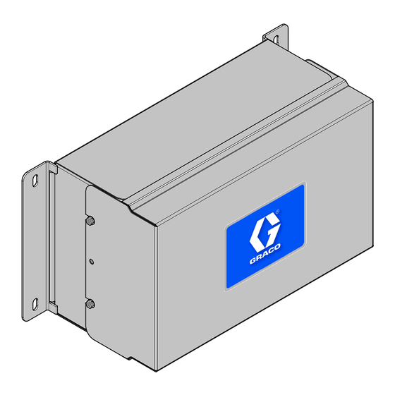
- Page 23 Replace AWI Board Replace AWI Board 5. Remove the screws and board (22). 6. Install the new board. reconnect the cable (15) and wires (17, 18). • To avoid electric shock, turn off power before servicing. • Shut off power at main circuit breaker. •...
- Page 24 Parts Parts Kit 15V337 Advanced Web Interface Module Wiring Diagrams Connect to 4. Connect to 10. Connect to 22. Ref. Part Description Qty. Ref. Part Description Qty. 15V339 PANEL 112443 BLOCK, terminal ground COVER 121994 CABLE, CAT5 15T752 — — — DIN RAIL —...
- Page 25 Parts Kit 15V336 Advanced Web Interface Server Hub Wiring Diagrams Connect to 4. Connect to 10. Ref. Part Description Qty. Ref. Part Description Qty. 15V339 PANEL 103833 SCREW, #10 —32 UNF-2A 4 COVER 112443 BLOCK, terminal ground 15T752 — — — DIN RAIL —...
- Page 26 Accessories Accessories Cables • 121998, CAT 5, RJ45 Cable, 25 ft (7.6 m) • 121999, CAT 5, RJ45 Cable, 50 ft (15 m) • 15V842, CAT 5, RJ45 Cable, 100 ft (30 m) • 15V843, CAT 5, RJ45 Cable, 200 ft (61 m) •...
- Page 27 Dimensions Dimensions 16.57 420.9 15.07 382.8 5.31 134.9 8.71 221.2 6.45 163.8 332459A Get other manuals https://www.bkmanuals.com...
-
Page 28: Graco Standard Warranty
Graco to be defective. This warranty applies only when the equipment is installed, operated and maintained in accordance with Graco’s written recommendations. This warranty does not cover, and Graco shall not be liable for general wear and tear, or any malfunction, damage or wear caused by faulty installation, misapplication, abrasion, corrosion, inadequate or improper maintenance, negligence, accident, tampering, or substitution of non-Graco component parts.
Need help?
Do you have a question about the 15V337 and is the answer not in the manual?
Questions and answers