Table of Contents
Advertisement
Quick Links
Advertisement
Table of Contents

Subscribe to Our Youtube Channel
Related Manuals for jbc PHBE


Summary of Contents for jbc PHBE
- Page 1 INSTRUCTION MANUAL PHBE Preheater for PCBs up to 36x28cm/14x11”...
-
Page 2: Packing List
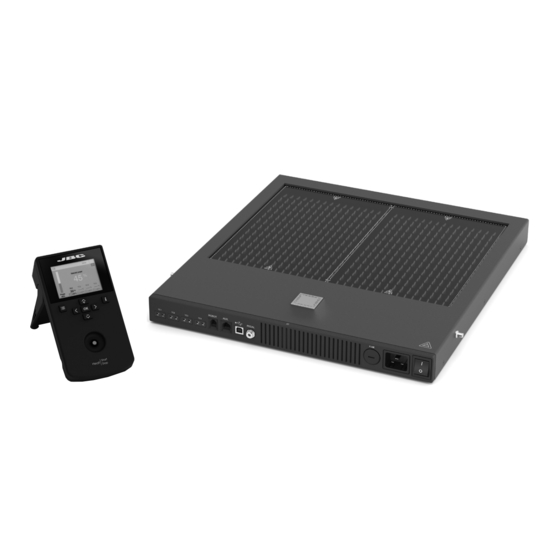
This manual corresponds to the following references: PHBE-9B (100V) PHBE-1B (120V) PHBE-2B (230V) Packing List The following items are included: PHBE Preheater Unit ......1 unit Console ............1 unit Ref. ACE-A RJ45 Cable ..........1 unit Power Cord ..........1 unit Ref. 0019914 Ref. - Page 3 para manuales - color gris 200 mm Features 130 mm 130 mm Preheater Unit 100 mm Heating Areas 80 mm Zone A Zone B Fuse 60 mm Fixing Brackets for PHBS Support Thermocouple 50 mm Connectors x4 Power RJ12 Connector 40 mm Power Socket (to Robot)
- Page 4 º º º º Power C 100 P 100 P 100 º º º P 100 º Work Display The console offers an intuitive user interface, which provides quick access to station parameters. 14:15 Status Indicator 14:15 Max. Rate Status Bar º...
-
Page 5: Recommended Guidelines
para manuales - color gris 200 mm Setting Thermocouples Function 130 mm 130 mm Select Thermocouples from the Work mode menu to set them up. The thermocouples (TC) can work in three different ways depending on what is needed. · Control: the unit maintains the selected temperature. 100 mm ·... -
Page 6: Work Mode
Max. Rate º 1.6ºC/s Selected 120 º 14:15 Work Mode º º º º Max. Rate Power C 100 P 100 P 100 º º º P 100 º º 1.6ºC/s Temperature Mode: Select Temp. mode from the Work mode menu. In this mode, the heater unit maintains the selected Selected 120 º... - Page 7 para manuales - color gris 200 mm Work Mode 130 mm 130 mm Temperature Mode: This function allows you to set a maximum value for the temperature increase per second when heating. Select Temp. mode from the Work mode menu. In this mode, the heater unit maintains the selected temperature for the TC1 thermocouple as long as the other TC’s do not reach the control/protection The maximum heating rate value can be set between 0.1ºC/s and 2.0ºC/s (2) or “None”...
- Page 8 º º º Profile Modes Select Profile Mode from the Work Mode Menu. In this mode the heater unit regulates the temperature of the TC1 thermocouple according to the selected profile as long as the other TCs do not reach the control/protection temperature limit.
-
Page 9: Profile Editor
JBC Predefined Profiles There are 3 profiles predefined by JBC: A, B and C. The difference between them is the number of steps: 2, 3 or 4. The thicker your PCB is and the more layers it contains, the more steps are needed to obtain gradual warming. -
Page 10: Process Analysis
Process Analysis By pressing Graphics in the main MENU, the temperature of TC1 thermocouple and power fi gures in real time are displayed. Graphics 14:15 Power (%) Temperature (ºC) Power [%] Ext. Temp [ºC] Switch Y Axis Between Power and Temperature System Notifications The following icons will be displayed on the screen’s status bar. - Page 11 USB-A connector to 80 mm export/import profiles. Update the Station Software 60 mm 1. Download the JBC Update File from 2. Insert the USB flash drive into the console. www.jbctools.com/software.html and save The icon is displayed while updating. it on a USB flash drive. (Preferably one with no 50 mm other files).
-
Page 12: Maintenance
- Only if it is absolutely necessary and if cleaning with isopropyl alcohol (IPA) is not enough, it is recommended to use a scraper to remove dirt in the glass area. - Replace any defective or damaged parts. Use original JBC spare parts only. - Repairs should only be performed by a JBC authorized technical service. - Page 13 para manuales - color gris 200 mm Safety 130 mm 130 mm It is imperative to follow safety guidelines to prevent electric shock, injury, fire or explosion. 100 mm - Do not use the units for any purpose other than PCB preheating. Incorrect use may cause a fire. - The mains cable must be plugged into approved bases.
- Page 14 Notes 14 14...
-
Page 15: Specifications
130 mm PHBE Preheater for PCBs up to 36x28cm/14x11” 100 mm Ref.: PHBE-9B 100V. Input 100V 50/60Hz Fuse 15A Ref.: PHBE-1B 120V. Input 120V 50/60Hz Fuse 15A Ref.: PHBE-2B 230V. Input 230V 50/60Hz Fuse 10A - Maximum Power: 80 mm Ref. - Page 16 In order for the warranty to be valid, equipment must be returned, postage paid, to the dealer where it was purchased. Get 1 extra year JBC warranty by registering here: https://www.jbctools.com/productregistration/ within 30 days of purchase. This product should not be thrown in the garbage.
Need help?
Do you have a question about the PHBE and is the answer not in the manual?
Questions and answers