Advertisement
Quick Links
CONTACT US FIRST
CONTACT US FIRST
sauder.com
sauder.com
sauder.com
BEFORE MAKING ANY RETURNS TO THE STORE.
BEFORE MAKING ANY RETURNS TO THE RETAILER.
sauder.com/service
Visit
Prefer the phone? Give us a ring at
Customer Service is available Monday-Friday - 8:30 a.m. to 5 p.m. EST (except holidays)
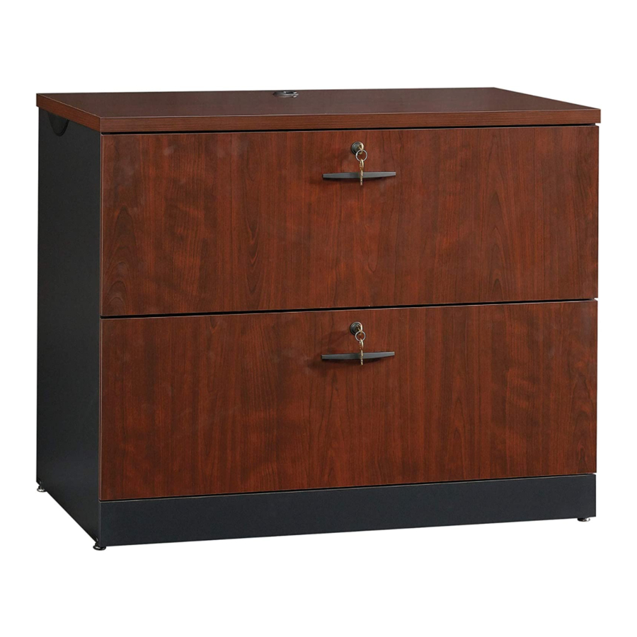
Lateral File
Via Collection | Model 419606
Sauder.com
Share your journey!
to order replacement parts, view video assembly tips, or chat with a live rep.
1-800-523-3987
.
Get all organized
and stuff.
NOTE: THIS INSTRUCTION
BOOKLET CONTAINS IMPORTANT
SAFETY INFORMATION.
PLEASE READ AND KEEP FOR
FUTURE REFERENCE.
English pg 1-24
Français pg 25-28
Español pg 29-32
Lot # 531257
Purchased: __________________
06/26/19
Advertisement

Related Manuals for Sauder Via 419606


Summary of Contents for Sauder Via 419606
- Page 1 CONTACT US FIRST CONTACT US FIRST sauder.com sauder.com sauder.com BEFORE MAKING ANY RETURNS TO THE STORE. BEFORE MAKING ANY RETURNS TO THE RETAILER. sauder.com/service Visit to order replacement parts, view video assembly tips, or chat with a live rep. 1-800-523-3987 Prefer the phone? Give us a ring at Customer Service is available Monday-Friday - 8:30 a.m.
- Page 2 Table of Contents Assembly Tools Required Part Identification No. 2 Phillips Screwdriver Tip Shown Actual Size Hardware Identification Assembly Steps 6-24 Hammer Not actual size Français 25-28 Español 29-32 Safety 33-34 Warranty Page 2 419606 www.sauder.com/service...
- Page 3 D498 RIGHT DRAWER SIDE (2) DRAWER FRONT (2) DRAWER BRACE (2) DRAWER BOTTOM (2) D499 DRAWER BACK (2) (Hidden part using recycled TOP (1) SHELF (1) material. Color may vary.) BOTTOM (1) BACK (1) D498 D499 D205 www.sauder.com/service 419606 Page 3...
- Page 4 METAL BRACKET - 5 ® LOCK INTERLOCK DRAWER LOCK LOCK - 2 MECHANISM - 1 ACTUATOR - 2 BRACKET - 2 COVER - 2 PROPEL NUT - 4 GROMMET CAP - 1 PULL - 2 CORD CLIP - 2 Page 4 419606 www.sauder.com/service...
- Page 5 BLACK 9/16" LARGE HEAD SCREW - 12 BROWN 7/16" LARGE HEAD SCREW - 16 BLACK 1/2" FLAT HEAD SCREW - 10 30S BLACK 1-9/16" FLAT HEAD SCREW - 10 BLACK 7/8" MACHINE SCREW - 4 BLACK 9/16" PAN HEAD SCREW - 11 www.sauder.com/service 419606 Page 5...
- Page 6 Assemble your unit on a carpeted floor or on the empty carton to avoid scratching your unit or the floor. Some assembly å To begin assembly, push a SAUDER TWIST-LOCK® (and snacks) required. FASTENER (7F) into the large holes in the BACK (F). å...
- Page 7 Turn two CAM SCREWS (8F) into the DRAWER FRONTS (H). å Push two HIDDEN CAMS (1F) into the DRAWER BRACES (M63). Arrow Arrow Hole The arrow in the HIDDEN CAM must point toward the hole in the edge of the board. www.sauder.com/service 419606 Page 7...
- Page 8 NOTE: Be sure to use the correct screw in this step. Use this hole. Open end BLACK 9/16" PAN HEAD SCREW (8 used in this step) This small hole must be here. Open end This small hole must be here. Page 8 419606 www.sauder.com/service...
- Page 9 ENDS (A and B) and BOTTOM (D). Use five BLACK 9/16" LARGE HEAD SCREWS (1S). å NOTE: Be sure the BRACKETS are even with the edges of the ENDS and BOTTOM. BLACK 9/16" LARGE HEAD SCREW (5 used for the METAL BRACKETS) www.sauder.com/service 419606 Page 9...
- Page 10 BRACKET and into the holes in the ENDS. Now, turn an ADJUSTABLE GLIDE (16E) into each PROPEL NUT. å NOTE: To raise a corner of the unit, turn the ADJUSTABLE GLIDE counter-clockwise. To lower a corner, turn the ADJUSTABLE GLIDE clockwise. Page 10 419606 www.sauder.com/service...
- Page 11 Step 6 å Fasten the BOTTOM (D) to the LEFT END (B). Tighten two TWIST-LOCK® FASTENERS. How to use the SAUDER TWIST-LOCK FASTENER ® 1. Insert the dowel end of the FASTENER into the hole of the adjoining part. NOTE: The dowel end of the FASTENER must remain fully inserted in the hole of the adjoining part while locking the FASTENER.
- Page 12 Fasten the BACK (F) to the LEFT END (B). Tighten two TWIST-LOCK® FASTENERS. Edge without TWIST-LOCK® FASTENERS i t h K ® f a c L O C S u r I S T - E R S T E N F A S Page 12 419606 www.sauder.com/service...
- Page 13 Fasten the SHELF (E) to the LEFT END (B). Tighten two TWIST-LOCK® FASTENERS. Notch S u r f a c I S T - i t h o F A S L O C T E N K ® E R S www.sauder.com/service 419606 Page 13...
- Page 14 Step 9 å Fasten the RIGHT END (A) to the BOTTOM (D), SHELF (E), and BACK (F). Tighten six TWIST-LOCK® FASTENERS. Edge with METAL Notch BRACKET Page 14 419606 www.sauder.com/service...
- Page 15 Use five BLACK 9/16" LARGE HEAD SCREWS (1S). your arms. å Fasten the LOCK BRACKET (5J) to the SHELF (E). Use a BLACK 9/16" LARGE HEAD SCREW (1S). BLACK 9/16" LARGE HEAD SCREW (6 used in this step) Long finished edge www.sauder.com/service 419606 Page 15...
- Page 16 Push two CORD CLIPS (9P) into the exact holes shown in the TOP (C). å Fasten a LOCK BRACKET (5J) to the TOP (C). Use a BLACK 9/16" LARGE HEAD SCREW (1S). BLACK 9/16" LARGE HEAD SCREW (1 used in this step) Page 16 419606 www.sauder.com/service...
- Page 17 Then, fasten the TOP (C) to the ENDS (A and B) and BACK (F). Tighten six TWIST-LOCK® FASTENERS. If you purchased the 419708 Hutch, follow Step 14 in the Hutch instructions at Large hole this time. www.sauder.com/service 419606 Page 17...
- Page 18 Fasten the DRAWER BRACE (M63) to the DRAWER SIDES (D205 and D498) and DRAWER BRACE (M63). FRONT (H). Tighten one HIDDEN CAM. Use five BLACK 1-9/16" FLAT HEAD SCREWS (30S). Repeat this step for the other DRAWER. Page 18 419606 www.sauder.com/service...
- Page 19 SIDES (D205 and D498). Use four BROWN 7/16" LARGE HEAD SCREWS (6S). å Repeat this step for the other drawer. Open end D205 Use this hole. Open end D498 BROWN 7/16" LARGE HEAD SCREW (8 used in this step) www.sauder.com/service 419606 Page 19...
- Page 20 Fasten the PULLS (12K) to the DRAWER FRONTS (H). Use four BLACK 7/8" MACHINE SCREWS (37S). BLACK 7/8" MACHINE SCREW (4 used for the PULLS) D498 D498 BLACK 1/2" FLAT HEAD SCREW (6 used for the ACTUATORS) Page 20 419606 www.sauder.com/service...
- Page 21 FRONT (H) and DRAWER BACK (D499). Use four Almost time to BROWN 7/16" LARGE HEAD SCREWS (6S). celebrate! With a nap. å Repeat this step for the other drawer. BROWN 7/16" LARGE HEAD SCREW (8 used for the FILE BRACKETS) D499 www.sauder.com/service 419606 Page 21...
- Page 22 Push a LOCK COVER (10J) over the key extension on the LOCK. å Repeat this step for the other drawer. Be sure the METAL Key extension BAR bends away from the KEY EXTENSION. BLACK 1/2" FLAT HEAD SCREW (4 used in this step) Metal bar Page 22 419606 www.sauder.com/service...
- Page 23 å Slide another FILE GLIDE (19B) onto the other end of the FILE RODS (18B), then press this FILE GLIDE over the LEFT DRAWER SIDE (D205). å Repeat this step for the other drawer. D205 D498 www.sauder.com/service 419606 Page 23...
- Page 24 NOTE: Please read the back pages of the instruction booklet for important safety information. å This completes assembly. Clean with a damp cloth. Wipe dry. And to celebrate, why not share your success story at sauder.com or The drawer with the DRAWER ACTUATOR fastened to the lower set of holes should be here.
- Page 25 élément et conserver le livret EXTRÉMITÉ DROITE ..........1 EXCENTRIQUE ESCAMOTABLE .....2 pour future référence. Pour contacter Sauder EXTRÉMITÉ GAUCHE ..........1 FIXATION TWIST-LOCK® ........18 en ce qui concerne cet B35 FOND DE TIROIR ............2 VIS D'EXCENTRIQUE ..........2 élément, faire référence...
- Page 26 Pour commencer l'assemblage, enfoncer une FIXATION faire tourner un PATIN RÉGLABLE (16E) dans chaque TOURILLON. TWIST-LOCK® SAUDER (7F) dans les gros trous de l'ARRIÈRE (F). REMARQUE : Pour soulever un coin de l'élément, faire tourner Répéter cette étape pour les EXTRÉMITÉS (A et B), le le PATIN RÉGLABLE dans le sens contraire des aiguilles d'une...
- Page 27 Enfoncer un COUVERCLE DE VERROU (10J) sur la extension de TIROIR (D205 et D498) et à l’ENTRETOISE DE TIROIR (M63). clé sur le VERROU. Utiliser cinq VIS TÊTE PLATE 40 mm NOIRES (30S). Répéter cette étape pour l'autre TIROIR. Répéter cette étape pour l'autre tiroir. www.sauder.com/service 419606 Page 27...
- Page 28 Répéter cette étape pour l'autre tiroir. les EXTRÉMITÉS (A et B). REMARQUE : Prière de lire les informations importantes sur la sécurité figurant sur les pages arrière du manuel d’instructions. Ceci complète l'assemblage. Nettoyer avec un tissu humide. Essuyer. Page 28 419606 www.sauder.com/service...
- Page 29 SUJETADOR TWIST-LOCK® ......18 su referencia futura. Si necesita ponerse en B35 FONDO DE CAJÓN ...........2 BIELA DE EXCÉNTRICO ........2 contacto con Sauder en PANEL SUPERIOR ............1 SOPORTE DE METAL ..........5 cuanto a esta unidad, FONDO .................1 34G MECANISMO DE UNIÓN ........1 refiérase al número...
- Page 30 MÉNSULA y dentro de los agujeros de los EXTREMOS. Para comenzar el ensamblaje, empuje un SUJETADOR Ahora, gire un DESLIZAMIENTO AJUSTABLE (16E) dentro de cada TWIST-LOCK® SAUDER (7F) dentro de los agujeros grandes TUERCA DE HÉLICE. del DORSO (F).
- Page 31 CAJÓN (D205 y D498) y a la RIOSTRA DE CAJÓN (M63). llave del SEGURO. Utilice cinco TORNILLOS NEGROS DE CABEZA PERDIDA de 40 mm (30S). Repita este paso para el otro CAJÓN. Repita este paso para el otro cajón. www.sauder.com/service 419606 Page 31...
- Page 32 EXTREMOS (A y B). NOTA: Por favor, lea las páginas de atrás del folleto de instrucciones en cuanto a importante información de seguridad. Esto completa el ensamblaje. Limpiar con un trapo húmedo. Seque con un paño. Page 32 419606 www.sauder.com/service...
- Page 33 Les téléviseurs peuvent être très un téléviseur. téléviseur. lourds. De plus, le poids et l’emplacement du tube image ont tendance à rendre les téléviseurs instables et enclins à tomber vers l’ a vant. www.sauder.com/service 419606 Page 33...
- Page 34 Además, el peso y la ubicación del tubo de imagen tienden a causar la inestabilidad de televisores y hacerlos propensos a volcarse hacia adelante. Page 34 419606 www.sauder.com/service...
- Page 35 à compter de la date d'achat la première fois et qui sont signalés à Sauder dans les limites de couverture de la contre tout défaut de matériaux ou de fabrication des composantes de mobilier Sauder.
- Page 36 BEFORE MAKING ANY RETURNS TO THE RETAILER. So, how did it go? Dear Valued Customer: Thanks so much for choosing Sauder® furniture. I hope the Set a world record for speed? purchase and assembly process was a positive experience Feeling good about yourself? and you feel good about the furniture you just built.
Need help?
Do you have a question about the Via 419606 and is the answer not in the manual?
Questions and answers