
Related Manuals for PCE Instruments UMI 840


Summary of Contents for PCE Instruments UMI 840
- Page 1 Bedienungsanleitung User Manual UMI 840 Durchflussmessgerät | Ultrasonic Flow Meter Letzte Änderung / last change: 6 September 2017 V 1.3...
-
Page 2: Table Of Contents
English Contents Safety notes Specifications Technical specifications Delivery contents Optional accessories System description Device Function keys Getting started Internal battery Power on Menu windows Operation Principle of measurement Configuration of parameters Sensors Data logger Calibration Maintenance Troubleshooting Warranty Disposal... -
Page 3: Safety Notes
Thank you for purchasing an ultrasonic flow meter from Dostmann electronic. Safety notes Please read this manual carefully and completely before you use the device for the first time. The device may only be used by qualified personnel and repaired by Dostmann electronic personnel. Damage or injuries caused by non-observance of the manual are excluded from our liability and not covered by our warranty. -
Page 4: Specifications
Specifications Technical specifications Hand-held device Model UMI 840 Measurement range -32 ... +32 m/s Resolution 0.0001 m/s for NPS ≥ 50 mm: ±1.5 % of reading Accuracy for NPS < 50 mm: ±3.5 % of reading Repeatability ±1.0 % of reading Media All liquids with an impurity of <5 % and a flow of >0.03m³/h... -
Page 5: Delivery Contents
Sensors Type of sensor Order no. UMI-S1 UMI-M1 sensor Order no. hand-held 6050-0840 6050-0841 device + sensor Sensor cable length Nominal DN 15 … DN 100 DN 50 … DN 700 diameter 20 … 108 mm 57 … 720 mm Liquid -30 …... -
Page 6: System Description
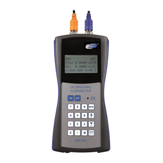
System description Device Top view Front view Bottom view Sensor connection (up) Sensor connection (down) Display LED charging lamp Membrane keypad Charging socket USB interface... - Page 7 Cable 5 m (2 x) Plug orange Plug blue Mains adaptor...
-
Page 8: Function Keys
Function keys The keypad consists of 18 keys. The keys from 0 to 9 and the decimal point are used to enter numbers Name Function Up / + key Press to select different window or enter numbers Down / - key Back key Press to go one step back or move cursor left ENTER key... -
Page 9: Menu Windows
After the start-up, the device will show window M01. This is the most common window und shows the positive totaliser, the volume flow, the flow velocity, the signal strength, the signal quality and the operating status, based on the values last set for the pipe. Menu windows M00 …... -
Page 10: Operation
/ sensors are placed on the pipes and are thus not subject to any wear and tear. The UMI 840 works with two signal transducers (sensors) which serve as ultrasonic transmitters and also as ultrasonic receivers. The sensors are installed on the outer wall of the pipe at a defined distance, one below the other. -
Page 11: Configuration Of Parameters
Configuration of parameters Menu Function View three totalisers (positive, negative, net), signal strength, signal quality and operating status View positive totaliser, volume flow, velocity, signal strength, signal quality and operating status View negative totaliser, volume flow, velocity, signal strength, signal quality and operating status View net totaliser, volume flow, velocity, signal strength, signal quality and operating status... - Page 12 9. Plug-in Type C 10. Standard-HS 11. Standard-HM 12. Standard-S1 13. π-Pipe 14. Standard-L1 15. Clamp-On TL-1 16. Standard-M Select sensor installation: 0. V method, 1. Z method, 2. N method, 3. W method View distance between sensors; should be stuck to as exactly as possible Save parameters to internal memory (18 memory locations) Read out saved parameters Select whether or not device should hold last good value when signal is...
-
Page 13: Sensors
Select memory 0. To RS232 1. To Buffer 2. Buffer => RS232 The RS232 signal is transmitted via the USB interface. View saved data in internal memory; navigate through data using Reset, Back, Up and Down keys; indication is updated automatically if logger has been activated View date and time (calendar for 99 years);... - Page 14 The first step before installation should be finding a suitable position to place the sensors. This is a requirement for accurate measurement results. Some basic knowledge about the pipes / the plumbing system is necessary. The ideal location would be an infinitely long, straight pipe, whereas there must be no entrapped air (air bubbles) in the liquid.
- Page 15 Sensor installation The UMI 840 has piezoelectric sensors which can transmit and also receive ultrasonic waves. The time the ultrasonic waves take to pass through the pipe walls and the liquid allows conclusions about the flow velocity.
- Page 16 Spacing between the sensors The distance between the upstream and the downstream sensor can be seen in window M25. The window states the inner distance between the two sensors which you should stick to as accurately as possible. The information in M25, however, must only be considered a coarse adjustment. The fine adjustment is carried out by arranging the spacing in a way that the time constant in M90 is exactly 100%.
- Page 17 Z method The Z method is recommended for pipe diameters of 300 to 500 mm. Top view of pipe Upstream transducer Spacing Flow direction Downstream transducer W method The W method is suitable for measurements of plastic pipes with diameters of 10 to 100 mm. Top view of pipe Upstream transducer Spacing...
-
Page 18: Data Logger
Data logger The internal memory of the device can save up to 1,800 values. (Each item selected in M50 is considered a value). To set or start the logger, do the following: (1) Via window M51, you can set the start time, the saving interval and the run time. This means that measurements can be taken for a maximum of 24 hours. - Page 19 Error codes and countermeasures Error codes are indicated by a single letter in the lower right corner of the display. However, these only occur in the menus M00, M01, M02, M03, M90 and M08. The following chart shows the error codes and countermeasures.
- Page 20 the display and the signal quality Q is ok, there must be a different error. In many cases, this means that the zero point has been set incorrectly. Go to menu M432 and reset the zero point. (2) The displayed volume flow is obviously too low or too high: a) Probably, the volume flow in window M44 has been entered manually.
-
Page 21: Warranty
Warranty You can read our warranty terms in our General Business Terms. Disposal For the disposal of batteries in the EU, the 2006/66/EC directive of the European Parliament applies. Due to the contained pollutants, batteries must not be disposed of as household waste. They must be given to collection points designed for that purpose.
Need help?
Do you have a question about the UMI 840 and is the answer not in the manual?
Questions and answers