Table of Contents
Advertisement
Quick Links
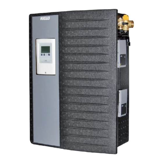
SC ACS 40 is an instantaneous domestic hot water production module that uses the working principle of a stainless steel
plates exchanger.
The setting of the domestic hot water outlet temperature (secondary side) happens with the modulation of the primary
circuit flow rate through a variable flow pump controlled by MFWC controller (PWM control).
Description
1 DHW mixer in packing
2 Instruction manual
3 Circulation pump assembling instructions
4 Immersion sensors
5 Fuse
At the end of its life, the product
should be not be disposed of
as solid urban waste, but rather
it should be handed over to a
differentiated
centre.
SC ACS 40
DESCRIPTION
CONTENTS OF KIT
Qty.
1
1
1
1
1
waste
collection
1
cod. Doc-0100459 - Rev. 1 (06/2021)
Advertisement
Table of Contents

Related Manuals for Riello SC ACS 40


Summary of Contents for Riello SC ACS 40
- Page 1 SC ACS 40 DESCRIPTION SC ACS 40 is an instantaneous domestic hot water production module that uses the working principle of a stainless steel plates exchanger. The setting of the domestic hot water outlet temperature (secondary side) happens with the modulation of the primary circuit flow rate through a variable flow pump controlled by MFWC controller (PWM control).
-
Page 2: General Safety Information And Precautions
GENERAL SAFETY INFORMATION AND PRECAUTIONS READ THIS MANUAL THOROUGHLY BEFORE PERFORMING ANY WORK ON THE PRODUCT. The manufacturer reserves the right to modify the product without notice for the purpose of introducing technical im- provements or to facilitate production, installation and positioning. The illustrations in this manual may therefore differ slightly from the actual product. -
Page 3: Main Components
MAIN COMPONENTS 1 Galvanised insulated backplate 2 Ball check valve, DN 20 3/4” F – 1” M 3 Ball valves, DN 20 3/4” F - 1" M 4 Pump (primary circuit) 5 Non-return valve (recirculation circuit) 6 Safety valve, 10 bar (secondary circuit) 7 Filling/drain cock, 1/2”... -
Page 4: Water Circuit
7 DN20 ball valve 4 Manual air vent 8 Safety valve TECHNICAL SPECIFICATIONS DESCRIPTION SC ACS 40 Thermal power supplied with storage cylinder at 50°C and DHW water delivery at 10-45°C Water draw at 10-45°C with storage cylinder at 50°C 29,5 l/min Thermal power absorbed with storage cylinder at 55°C and DHW water delivery at 10-45°C... - Page 5 Domestic hot water production graph Mandata primario (°C) Primary inlet (°C) NB: Correct functioning of the product is only guaranteed if the primary circuit inlet temperature is at least 5°C higher than the DHW setpoint.
- Page 6 DIMENSIONS AND FITTINGS 1” M 3/4” F UACS EAFS SC ACS 40 MP - Primary inlet 1 M - 3/4" F RP - Primary outlet (return) 1 M - 3/4" F EAFS - Domestic cold water inlet 1 M - 3/4" F UACS - DHW outlet 1 M - 3/4"...
-
Page 7: Wiring Diagram
WIRING DIAGRAM PWM1 Primary circuit pump Not used PWM2 Recirculation pump Ground PT1000 Recirculation (S1 optional) phase line L / primary pump PT1000 DCW (S2) Neutral line N / primary pump PT1000 primary circuit (S3) Connect to controller terminal VFS1 Puffer high PT1000 Low voltage max. -
Page 8: System Schematic
SYSTEM SCHEMATIC Example of wall mounted installation Recirculation Primary inlet DHW outlet Cold water inlet Primary outlet (return) In case of recirculation, provide an expansion tank suitably sized in order to avoid overpressure due to thermal expansion and water hammer. INSTALLATION PRELIMINARY CHECKS Before every operation carefully remove the packaging and verify if there is external damages. -
Page 9: Installation On The Wall
Installation and connection of the product must be performed by an authorised, specialist company. The company installing the product assumes all responsibility for ensuring that the installation and functioning of the product conform to applicable standards. The product must be stored in a dry place where it is not subject to frost. - Page 10 Total hardness °Fr 7-15 Conductivity μS/cm 10…500 The SC ACS 40 hot water mixer is made from materials Solid substances mg/l <30 that conform to the requirements of Ministerial Decree Free chlorine mg/l <0.5 174/2004 (Italy) implementing Council Directive 98/83/...
-
Page 11: Putting Into Service
ELECTRICAL CONNECTIONS The following instructions are mandatory. 1 Use a multi-pole, magnetic thermal, earth leakage breaker and disconnector that conforms to legislation in the coun- try of installation. 2 Respect the L (Phase) - N (Neutral) polarity. Keep the ground wire about 2 cm longer than the power wires. 3 Make sure the product is correctly connected to ground. -
Page 12: Flushing The Heat Exchanger
FLUSHING THE HEAT EXCHANGER - Shut off the DHW flow by closing the ball valves (1a) and (1b) for the cold water inlet and hot water outlet respectively. - Attach the flushing fluid supply to the cold water inlet valve (2b). - Attach the flushing fluid drain to the DHW outlet valve (2a). -
Page 13: About The Controller
- The manufacturer’s name plate and other factory marks applied to the controller must not be altered, removed or made illegible. - Only the settings described in these instructions are able to guarantee the correct operation of the controller. ABOUT THE CONTROLLER The MFWC controller enables efficient use and operational control of the mixer system. -
Page 14: Terminal Connection Diagram
Other specifications and dimensions Housing ..........3-part, ABS plastic Overall dimensions . -
Page 15: Menu Sequence And Menu Structure
DISPLAY AND PROGRAMMING Display The display (1), with full text and graphics mode, is self-explanatory to all intents and purposes, making the controller easy to use. The LED (2) lights up green when a relay is activated. The LED (2) lights up red when the operating mode is "Off". -
Page 16: Commissioning Help
The following menus are available 1. Measured values Measured sensor values 2. Statistics Operating hours counters 3. Operating mode Automatic mode, manual mode, or controller Off 4. Settings Management of parameters required for normal operation 5. Protections Functions for preventing damage to the system and injury to users 6. -
Page 17: Measured Values
1.MEASURED VALUES Menu “1. Measured values” indicates the current temper- 1.Exit Measured values atures measured. Quit the menu by pressing “esc” or se- lecting “Exit Measured values”. 1.1.Hot water 0°C Selecting “Info”, a short message will appear explaining 1.2.Flow rate 0 l/min the measurement values. -
Page 18: Operating Mode
3. OPERATING MODE Menu “3. Operating mode” allows selection of the desired 3.Exit operating mode mode of operation: automatic, off, or manual. To quit the menu, press “esc” or select “Exit operating 3.1.Auto mode”. 3.2.Manual 3.1 Automatic Info Automatic is the normal operating mode of the controller. Only automatic mode guarantees correct operation of the system, taking account of the current temperatures and the selected parameter settings! -
Page 19: Protective Functions
Settings range: 10 °C to 85 °C 4.4.3 Recirculation hysteresis - switch-off hysteresis of the circulation pump If temperature exceeds Tmin at S2, the pump is switched off. Settings range: 1-5K / Default: see table. 4.4.4 Maximum recirculation flow - maximum fl ow rate of the circulation pump If the flow rate measured at sensor 6 exceeds this value (because water is being drained from the system) the circulation pump is switched off. -
Page 20: Special Functions
The AL function is switched off by default. A message containing the date is shown as soon as the AL function terminates successfully. We recommend to set the „AL start time“ in a period where little or no withdrawal of water takes place. - Page 21 This signal is needed to switch on the pump at minimum speed. Settings range: (Solar:) 0 ...50 % / Default: 10 % - (Heating:) 50 % ... 100 % / Default: See table 6.1.6. PWM Max This determines the output signal for operation of the pump at maximum speed, used for example when purging the system or in manual mode.
- Page 22 This function activates the selected relay with a 0-10V / PMW V1 output in parallel to V1. High efficiency pumps with a 0-10V / PWM signal can be powered using the additional function “Always on” or “Parallel functioning V1/V2” via relays 1-3. 6.5.4.1.
- Page 23 6.13. Time and date This menu is used to set the current time and date. To run analyses on system data, the time must be set correctly at the controller. Remember that the clock will stop if the power supply to the controller is cut off for more than about 24 hours, and must then be reset. 6.14.
-
Page 24: Malfunctions And Error Messages
MALFUNCTIONS MALFUNCTIONS AND ERROR MESSAGES If the controller detects a malfunction, the red LED blinks and the warning symbol appears on the display. If the malfunction resolves itself, the warning symbol becomes an information symbol and the red LED stops (Flashing LED + blinking. -
Page 25: Special Function
DEFAULT PARAMETER SETTINGS TABLE SETTINGS RAN- DEFAULT USER NOTE MENU DESCRIPTION DESCRIPTION SC ACS 40 NOTE 4. SETTINGS Tset 30°C ÷ 85°C 45°C T max. 50°C ÷ 95°C 60°C 1÷12 / 1÷20 / 2÷40 / VFS type 2÷40 l/min 5÷100 / 10÷200 / 200÷400 l/min... -
Page 26: Menu Description
SETTINGS RAN- DEFAULT USER NOTE MENU DESCRIPTION DESCRIPTION SC ACS 40 NOTE Pump V2 6.3.1 Pump type 0 - 10V / PWM PWM 1 Solar / Heating/ 6.3.2 Pump Profile 1-11 / Solar Manual 6.3.3 Output signal Normal / inverted... - Page 27 CHECKS On completion of the installation, perform the checks listed in the table below. DESCRIPTION All automatic or manual filling pumps removed. Safety valve calibrated to 6 bar, and flow open. Drain pipe from safety valve routed suitably. Expansion vessel correctly located and pre-charged to 2.5 bar RECIRCULATION PARAMETERS SETTINGS - Preliminary checks: - Check the PWM cable connection of the circulation pump (2-wire cable) brown (terminal V2) / blue - terminal (-).
- Page 28 RIELLO S.p.A. Via Ing. Pilade Riello, 7 37045 - Legnago (VR) www.riello.com The manufacturer strives to continuously improve all products. Appearance, dimensions, technical specifi cations, standard equipment and accessories are therefore liable to modifi cation without notice.
Need help?
Do you have a question about the SC ACS 40 and is the answer not in the manual?
Questions and answers