Table of Contents
Advertisement
Advertisement
Chapters
Table of Contents

Related Manuals for Midea mcd-24hrdn1


Summary of Contents for Midea mcd-24hrdn1
- Page 1 DC INVERTER SERIES Service Manual 2013 LIS-B-1306...
- Page 3 Contents Part 1 General Information ..................... 1 Part 2 Indoor Units ......................8 Part 3 Outdoor Units ....................116 Part 4 Installation ......................133 Part 5 Electrical Control System ................177 ※The specifications, designs, and information in this book are subject to change without notice for product improvement.
-
Page 5: Table Of Contents
General Information Part 1 General Information 1. Model Lists ....................2 2. External Appearance ................... 4 2.1 Indoor Units ..................4 2.2 Outdoor Units ..................5 3. Nomenclature ....................6 4. Features ......................7 General Information... -
Page 6: Model Lists
MCA2-12HRDN1-Q MFA-12HRDN1-Q MOU-12HDN1-Q Rotary DC Inverter GMCC MUB-12HRDN1-Q MTB1-12HWDN1-Q MCA2-18HRDN1-Q MCD-18HRDN1-Q MOU-18HDN1-Q Scroll DC Inverter GMCC MFA-18HRDN1-Q MUB-18HRDN1-Q MTB-18HWDN1-Q MCC-24HRDN1-Q MCD-24HRDN1-Q MOU-24HDN1-Q Rotary DC Inverter GMCC MUB-24HRDN1-Q MTB-24HWDN1-Q MFGA-24ARDN1-QC2 MCC-30HRDN1-Q MCD-30HRDN1-Q MOU-30HDN1-Q Rotary DC Inverter MITSUBISHI MUB-30HRDN1-Q MTB-30HWDN1-Q MCC-36HRDN1-Q MCD-36HRDN1-Q... - Page 7 Model Lists MUB-48HRDN1-Q MUE-48HRDN1-Q MTB-48HWDN1-Q MHD-48HRDN1-Q MFGA-48ARDN1-R MCC-60HRDN1-R MCD-60HRDN1-Q MUB-60HRDN1-R GUANGZHOU MOU-60HDN1-R Rotary DC Inverter MUE-60HRDN1-Q MITSUBISHI MTB-60HWDN1-R MHD-60HRDN1-R MFGA-60ARDN1-R MOU-60HDN1-R Rotary DC Inverter GMCC MTB-60HWDN1-R General Information...
-
Page 8: External Appearance
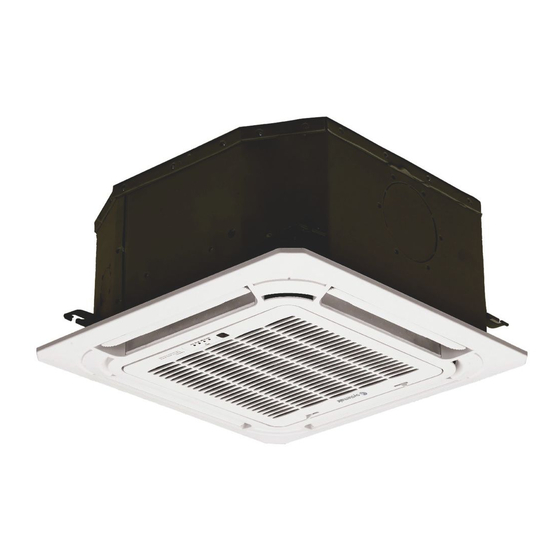
External Appearance 2. External Appearance 2.1 Indoor Units Duct Ceiling & Floor Four-way Cassette Compact Four-way cassette Super-slim Four-way Cassette GA Floor Standing Console High static pressure duct generation ceiling-floor General Information... -
Page 9: Outdoor Units
External Appearance 2.2 Outdoor Units Single fan outdoor unit Double fan outdoor unit Double fan outdoor unit General Information... -
Page 10: Nomenclature
V AHU Type T Duct Type F Console Type U Ceiling & Floor Type H High Static Pressure Duct Type Midea 3.2 Outdoor Unit M O U T- 36 H D N1- R RC4 Energy Efficiency Code Power Supply Q 220~240V,1N, 50HZ... -
Page 11: Features
Features 4. Features 4.1 Universal outdoor unit design Indoor unit with the same capacity can match with the same outdoor unit. 4.2 High efficiency and energy saving. Thanks to the DC inverter technology and optimized piping system, the EER and COP of whole series can easily reach A-class. - Page 12 Indoor Units Part 2 Indoor Units New Four-way Cassette Type (Compact) ......9 Four-way Cassette Type ............. 19 Super Slim Cassette Type ..........27 Duct Type ................41 Ceiling & Floor Type ............57 Console Type ............... 71 High Static Pressure Duct ..........85 Generation Ceiling &...
- Page 13 New Four-way Cassette Type (Compact) New Four-way Cassette Type (Compact) 1. Features ....................10 2. Dimensions ................... 11 3. Service Space..................12 4. Wiring Diagrams ................... 13 5. Air Velocity and Temperature Distributions(Reference Data) ..14 6. Electric Characteristics ................ 15 7.
-
Page 14: Features
Features 1. Features 1.1 New panel 360°surrounding air outlet design, affords comfortable feeling 1.2 Compact design The body size is 570×260×570mm, it’s just smaller than the ceiling board, so it’s very easy for installation and will not damage the decoration. The panel size is 647×50×647mm. ... -
Page 15: Dimensions
Dimensions 2. Dimensions... -
Page 16: Service Space
Service Space 3. Service Space... -
Page 17: Wiring Diagrams
Wiring Diagrams 4. Wiring Diagrams MCA2-12HRDN1-Q MCA2-18HRDN1-Q... -
Page 18: Air Velocity And Temperature Distributions(Reference Data)
Air Velocity and Temperature Distributions(Reference Data) 5. Air Velocity and Temperature Distribution s(Reference Data) Airflow velocity Temperature... -
Page 19: Electric Characteristics
Electric Characteristics 6. Electric Characteristics Power Indoor Units Supply Model Voltage Min. Max. MCA2-12HRDN1-Q 220-240V 198V 254V MCA2-18HRDN1-Q 220-240V 198V 254V Notes: MFA: Max. Fuse Amps. (A) 7. Sound Levels 1.4m Microphone Noise level dB(A) Model MCA2-12HRDN1-Q MCA2-18HRDN1-Q... -
Page 20: Accessories
Accessories 8. Accessories Name Shape Quantity 1. Expansible hook Installation fittings 2. Installation hook 3. Installation paper board 4. Out-let pipe sheath 5. Out-let pipe clasp Drainpipe Fittings 6. Tightening band 7. Drain joint 8. Remote controller Remote controller & Its 9. -
Page 21: Field Wiring
Field Wiring 10. Field Wiring MCA2-12HRDN1-Q MCA2-18HRDN1-Q... - Page 22 Field Wiring MCA2-12HRDN1-Q MCA2-18HRDN1-Q...
-
Page 23: Features
Four-way Cassette Type Four-way Cassette Type 1. Features ....................22 2. Dimensions ................... 25 3. Service Space..................26 4. Wiring Diagrams ................... 27 5. Air Velocity and Temperature Distributions(Reference Data) ..22 6. Electric Characteristics ................ 23 7. Sound Levels ..................23 8. -
Page 24: Features
Features 1. Features 1.1 New panel (60k standard) New panel with 360° airflow supply Air intake grille lift function for supper thin cassette, convenient for maintenance. 1.2 3D screw fan technology 3D screw indoor fan technology reduces the air resistance, increases the air volume and improves the heat exchange efficiency. - Page 25 Features 1.3 Fresh air intake function Fresh air fulfills air quality more healthy and comfortable. Fresh Dimension:Φ75mm 1.4 Air passage function Reserves the space for air outlet from the side of indoor unit; It’s availed to connect air duct from side to nearby small rooms.
-
Page 26: Features
Features 1.5 Drainage pump Build-in water pump which pumping head is 750mm upmost. It’s convenient to install drainage piping under most space condition. 1.6 LED display Digital LED interface, makes the unit more elegant. Normally display the setting temperature ... -
Page 27: Dimensions
Dimensions Dimensions Unit: mm MODEL(Btu/h) 24000 Ф15.9 Ф9.5 >260 30000 Ф15.9 Ф9.5 >330 36000 Ф15.9 Ф9.5 >330 48000 Ф15.9 Ф9.5 >330 60000 Ф15.9 Ф9.5 >330 Four-way Cassette Type... -
Page 28: Service Space
Service Space Service Space >1000m m >1000mm Four-way Cassette Type... -
Page 29: Wiring Diagrams
Wiring Diagrams Wiring Diagrams MCC-24HRDN1-Q MCC-30HRDN1-Q Four-way Cassette Type... - Page 31 Wiring Diagrams MCC-36HRDN1-Q MCC-48HRDN1-Q MCC-60HRDN1-R Four-way Cassette Type...
-
Page 32: Air Velocity And Temperature Distributions(Reference Data)
Air Velocity and Temperature Distributions(Reference Data) Air Velocity and Temperature Distributions(Reference Data) Airflow velocity Condenser Evaporator Electronic Condenser temp. sensor expansion valve Evaporator temp. sensor High pressure switch Filter Filter Capillary Room temp. sensor Discharge temp. sensor Oil separator Ambient temp. sensor 4-way valve Filter Oil return... -
Page 33: Electric Characteristics
Four-way Cassette Type Electric Characteristics Power Indoor Unit Supply Model Voltage MCC-24HRDN1-Q 220-240 MCC-30HRDN1-Q 220-240 MCC-36HRDN1-Q 220-240 MCC-48HRDN1-Q 220-240 MCC-60HRDN1-R 220-240 Notes: MFA: Max. Fuse Amps. (A) Sound Levels 1.4m Microphone Noise level dB(A) Model MCC-24HRDN1-Q MCC-30HRDN1-Q MCC-36HRDN1-Q MCC-48HRDN1-Q 42.5 MCC-60HRDN1-R Four-way Cassette Type... - Page 34 Accessories Accessories Name Shape Quantity INSTALLATION FITTINGS Installation paper board Soundproof / insulation sheath Tubing & Fittings Connecting pipe group Out-let pipe sheath Out-let pipe clasp Drainpipe Fittings Drain joint Seal ring Remote controller & Its Frame Remote controller & Its Remote controller holder Frame Mounting screw(ST2.9×10-C-H)
-
Page 35: Four-Way Cassette Type
Four-way Cassette Type The Specification of Power Model 18000-30000Btu/h 36000-60000 Btu/h 30000-60000 Btu/h Phase 1-phase 1-phase 1-phase Frequency and Voltage 220-240V, 50Hz 220-240V, 50Hz 220-240V, 50Hz INDOOR UNIT POWER POWER WIRING (mm 3×1.0 3×1.0 3×1.0 CIRCUIT BREAKER (A) Phase 1-phase 1-phase 3-phase Frequency and Voltage... - Page 36 Field Wiring Field Wiring Wiring chart Four-way Cassette Type...
- Page 37 Super Slim Cassette Type Super Slim Cassette Type Features ....................28 Dimensions ..................32 Service Space ..................33 Wiring Diagrams .................. 34 Air Velocity and Temperature Distributions(Reference Data) ..35 Electric Characteristics...............
- Page 38 Features 1. Features Overview Compact design, super slim body size, less space requiring in installation Each louver can be separately controlled, more comfort air blowing is possible. Auto-lifting panel design, more convenient to clean and maintain the filter. (optional) Old Cassette New slim cassette Volume change...
- Page 39 Features New air-intake Optional ionizer generator Ionizer generator is optional to get refreshing air to your room. Ionizer can be switched on or off by remote controller. When pressing the Clean Air button on the remote controller, Ionizer will work and the indicator light on display board will shine.
- Page 40 Features External air duct design Reserve external air duct, more flexible for the air supply. Built-in draining pump Due to the improvement of structure, more convenient to repair or replace the draining pump. Draining Pump Built-in draining pump to make sure condensed water drain out reliably. Super Slim Cassette Type...
-
Page 41: Part
Features Terminals for alarm lamp and long-distance on-off controller connection are standard Reserve terminals for the connection of alarm lamp and long-distance on-off controller, more human control. Alarm lamp Long-distance on-off controller Optional touch screen wired controller Touch screen wired controller is optional, with error code indication function. Better man-machine conversation interface. - Page 42 Dimensions 2. Dimensions Model 18-30 >235 36-48 >275 >312 Super Slim Cassette Type...
-
Page 43: Super Slim Cassette Type
Service Space 3. Service Space >1000mm >1000mm Super Slim Cassette Type... - Page 44 Wiring Diagrams 4. Wiring Diagrams MCD-18HRDN1-Q MCD-24HRDN1-Q MCD-30HRDN1-Q MCD-36HRDN1-Q MCD-48HRDN1-Q MCD-60HRDN1-Q Super Slim Cassette Type...
- Page 45 Air Velocity and Temperature Distributions(Reference Data) 5. Air Velocity and Temperature Distributions(Reference Data) Airflow velocity Condenser Evaporator Electronic Condenser temp. sensor expansion valve Evaporator temp. sensor High pressure switch Filter Filter Capillary Room temp. sensor Discharge temp. sensor Oil separator Ambient temp.
- Page 46 Electric Characteristics 6. Electric Characteristics Power Indoor Unit Supply Model Voltage 220-240 MCD-18HRDN1-Q 220-240 MCD-24HRDN1-Q 220-240 MCD-30HRDN1-Q 220-240 MCD-36HRDN1-Q 220-240 MCD-48HRDN1-Q 220-240 MCD-60HRDN1-Q Notes: MFA: Max. Fuse Amps. (A) Super Slim Cassette Type...
- Page 47 Sound Levels 7. Sound Levels 1.4m Microphone Noise level dB(A) Model MCD-18HRDN1-Q MCD-24HRDN1-Q MCD-30HRDN1-Q MCD-36HRDN1-Q MCD-48HRDN1-Q MCD-60HRDN1-Q Super Slim Cassette Type...
-
Page 48: Accessories
Accessories 8. Accessories Name Shape Quantity Installation paper board INSTALLATION FITTINGS Bolt M5 Tubing & Fittings Soundproof / insulation sheath Out-let pipe Out-let pipe sheath Drainpipe Fittings Out-let pipe clasp Remote controller & Its Frame Remote controller holder Remote controller & Its Frame Mounting screw(ST2.9×10-C-H) Remote controller manual... -
Page 49: The Specification Of Power
The Specification of Power 9. The Specification of Power Model 18000-24000Btu/h 30000-60000 Btu/h Phase 1-phase 1-phase Frequency and Voltage 220-240V, 50Hz 220-240V, 50Hz INDOOR UNIT POWER POWER WIRING (mm 3×1.0 3×1.0 CIRCUIT BREAKER (A) Phase 1-phase 1-phase Frequency and Voltage 220-240V, 50H 220-240V, 50H OUTDOOR UNIT POWER... -
Page 50: Field Wiring
Field Wiring 10. Field Wiring MCD-18HRDN1-Q MCD-24HRDN1-Q MCD-30HRDN1-Q MCD-36HRDN1-Q MCD-48HRDN1-Q MCD-60HRDN1-Q Super Slim Cassette Type... - Page 51 Duct Type Duct Type 1. Features ......................42 2. Dimensions ....................45 3. Service Space ....................46 4. Wiring Diagrams ................... 47 5. Static Pressure ..................... 49 6. Electric Characteristics ................51 7. Sound Levels ....................52 8. Accessories ....................53 9.
-
Page 52: Features
Features 1. Features 1.1 Installation accessories: (Optional) Front Board, Canvas Air Passage, Filter, Panel, for easy installation Front Board Canvas Air Passage Filter Panel 1.2 Easy Installation: Two air inlet styles (Bottom side or Rear side) Air inlet from rear is standard for all capacity; air inlet from bottom is optional. ... - Page 53 Features Replace the motor or centrifugal fan Remove the ventilated panel firstly. Remove a half of blower housing and take out the motor with centrifugal fan. Directly remove two bolts, and then replace the motor or centrifugal fan easily. Motor Blower Housing Ventilated Panel...
- Page 54 Features 1.7 Built-in display board The standard indoor unit can be controlled by wired controller. There is a display board with a receiver in the E-box. Move out the display, and fix it in other place, even in the distance of 10m. The unit will realized remoter control. ...
-
Page 55: Dimensions
Dimensions 2. Dimensions Size of outline Outline dimension(mm) Air outlet opening size Air return opening size dimension mounted Capacity plug (KBtu) 210 635 570 210 635 570 270 635 570 30/36 1140 270 775 710 1035 1180 48/60 1200 300 865 800 1094 1240 Duct Type... -
Page 56: Service Space
Service Space 3. Service Space Ensure enough space required for installation and maintenance. All the indoor units reserve the hole to joint the fresh air pipe. The hole size as following: Duct Type... -
Page 57: Wiring Diagrams
Wiring Diagrams 4. Wiring Diagrams MTB1-12HWDN1-Q MTB-18HWDN1-Q 、MTB-24HWDN1-Q、MTB-30HWDN1-Q Duct Type... - Page 58 Wiring Diagrams MTB-36HWDN1-Q MTB-48HWDN1-Q MTB-60HWDN1-R Duct Type...
-
Page 59: Static Pressure
Static Pressure 5. Static Pressure 12,000Btu/h 18,000Btu/h Super high speed High speed Super high speed Mid speed High speed Mid speed Low speed Low speed 600 700 800 900 1000 1100 1200 Air volume(m /h) Air volume(m /h) 24,000Btu/h 36,000Btu/h Super high speed Super high speed High speed... - Page 60 Static Pressure 48,000Btu/h 60,000Btu/h Super high speed Super high speed High speed High speed Mid speed Low speed Mid speed Low speed 2200 2500 1000 1300 1600 1900 2800 3100 3400 1000 1300 1600 1900 2200 2500 2800 3100 Air volume(m /h) Air volume(m /h) Duct Type...
-
Page 61: Electric Characteristics
Electric Characteristics 6. Electric Characteristics Indoor Unit Power Supply Model Voltage Min. Max. MTB1-12HWDN1-Q 220-240 MTB-18HWDN1-Q 220-240 MTB-24HWDN1-Q 220-240 MTB-30HWDN1-Q 220-240 MTB-36HWDN1-Q 220-240 MTB-48HWDN1-Q 220-240 MTB-60HWDN1-R 220-240 Notes: MFA: Max. Fuse Amps. (A) Duct Type... -
Page 62: Sound Levels
Sound Levels 7. Sound Levels Concealed Duct Type Discharge Suction Duct Duct 1.4m Microphone Noise level dB(A) Model MTB1-12HWDN1-Q MTB-18HWDN1-Q MTB-24HWDN1-Q MTB-30HWDN1-Q MTB-36HWDN1-Q MTB-48HWDN1-Q MTB-60HWDN1-R Duct Type... -
Page 63: Accessories
Accessories Accessories Name Shape Quantity Soundproof / insulation sheath Tubing & Fittings Binding tape Seal sponge Drain joint Drainpipe Fittings (for cooling & heating) Seal ring Wired controller & Its Frame Wired controller Owner , s manual Others Installation manual Magnetic ring (twist the electric wires L EMS &... -
Page 64: The Specification Of Power
The Specification of Power 9. The Specification of Power 36000-60000 30000-60000 Model 12000Btu/h 18000-30000Btu/h Btu/h Btu/h Phase 1-phase 1-phase 1-phase 1-phase Frequency and 220-240V, 50Hz 220-240V, 50Hz 220-240V, 50Hz 220-240V, 50Hz Voltage INDOOR UNIT POWER WIRING POWER 3×1.5 3×1.0 3×1.0 3×1.0 CIRCUIT BREAKER Phase... -
Page 65: Field Wiring
Field Wiring 10. Field Wiring Duct Type... - Page 66 Field Wiring Air-conditioner link-circuit. For model 12 For model 18-60 Duct Type...
- Page 67 Ceiling & Floor Type Ceiling & Floor Type 1. Features ....................58 2. Dimensions ................... 60 3. Service Space..................61 4. Wiring Diagrams ................... 61 5. Air Velocity and Temperature Distributions(Reference Data) ..64 6. Electric Characteristics ................ 66 7. Sound Levels ..................66 8.
-
Page 68: Features
Features 1. Features 1.1 Two-way installation The rounded design of the ceiling and floor type air conditioner allows either ceiling or floor-level installation. Ceiling installation saves room space, while floor installation helps prevent the loss of warm air. 1.2 Brief design ... - Page 69 Features 1.4 Optional drainage pipe connection Both right side and left side drainage holes are available to avoid the space limitation for drainage pipe installation. Make you more convenient during installation. 1.5 Five panels for optional Standard Panel A Panel B Panel (LED display) C Panel (LED display) D Panel...
-
Page 70: Dimensions
Dimensions 2. Dimensions a. Wall mounting installation b. Ceiling installation Capacity (Btu/h) 12000-24000 36000 1280 1195 48000-60000 1670 1070 1542 Notes: The dimension of 12000Btu/h and 24000Btu/h are the same The dimension of 48000Btu/h and 60000Btu/h are the same Ceiling & Floor Type... -
Page 71: Service Space
Service Space 3. Service Space ≥35mm ≥1000mm 4. Wiring Diagrams MUB-12HRDN1-Q Ceiling & Floor Type... - Page 72 Wiring Diagrams MUB-18HRDN1-Q、MUB-24HRDN1-Q MUB-30HRDN1-Q Ceiling & Floor Type...
-
Page 73: Ceiling & Floor Type
Wiring Diagrams MUB-36HRDN1-Q MUB-48HRDN1-Q MUB-60HRDN1-R Remark: SW1:Temperature selection of anti-cold-air function SW2: Floor or Ceiling installation selection SW3: Temperature compensation selection. The default temperature compensation value is 1℃ for floor installation and 6℃ for ceiling installation, and can not be changed by the user. If the other temperature required, modification should be done in factory. - Page 74 Air Velocity and Temperature Distributions(Reference Data) 5. Air Velocity and Temperature Distributions(Reference Data) Discharge angle 60° (CEILING) Airflow velocity Condenser Evaporator Electronic Condenser temp. sensor expansion valve Evaporator temp. sensor High pressure switch Filter Filter Capillary Room temp. sensor Discharge temp. sensor Oil separator Ambient temp.
- Page 75 Air Velocity and Temperature Distributions(Reference Data) Discharge angle 60°(FLOOR) Airflow velocity Temperature Ceiling & Floor Type...
-
Page 76: Electric Characteristics
Electric Characteristics 6. Electric Characteristics Indoor Unit Power Supply Model Voltage MUB-12HRDN1-Q 220~240 MUB-18HRDN1-Q 220~240 MUB-24HRDN1-Q 220~240 MUB-30HRDN1-Q 220~240 MUB-36HRDN1-Q 220~240 MUB-48HRDN1-Q 220~240 MUB-60HRDN1-R 220~240 Notes: MFA: Max. Fuse Amps. (A) 7. Sound Levels Microphone 1.5m Air outlet side Microphone Ceiling Floor Noise level dB(A) -
Page 77: Accessories
Accessories 8. Accessories Name Shape Quantity 1.Hook Installation fittings 2.Hanging arm 3. Remote controller Remote controller & Its 4. Remote controller holder holder 5. Mounting screw (ST2.9×10-C-H) 6. Alkaline dry batteries (AM4) 7. Owner's manual Others 8. Installation manual 9. Remote controller manual Ceiling &... -
Page 78: The Specification Of Power
The Specification of Power 9. The Specification of Power 36000-60000 30000-60000 Model 12000Btu/h 18000-30000Btu/h Btu/h Btu/h Phase 1-phase 1-phase 1-phase 1-phase Frequency and 220-240V, 50Hz 220-240V, 50Hz 220-240V, 50Hz 220-240V, 50Hz Voltage INDOOR UNIT POWER WIRING POWER 3×1.5 3×1.0 3×1.0 3×1.0 CIRCUIT BREAKER Phase... -
Page 79: Field Wiring
Field Wiring 10. Field Wiring Ceiling & Floor Type... - Page 80 Field Wiring For model 12 For model 18~60 Ceiling & Floor Type...
- Page 81 Console Type Console Type 1. Features ....................73 2. Dimensions ................... 76 3. Service Space..................77 4. Wiring Diagrams ................... 78 5. Air Velocity and Temperature Distributions(Reference Data) ..79 6. Electric Characteristics ................ 80 7. Sound Levels ..................81 8.
-
Page 83: Features
Features 1. Features 1.1. Modern and elegant appearance The simple and stylish designs can nicely harmonies with your living space. 1.2. Four panels optional 1.3. Two air-outlet ways Cooling mode Quick Cooling To maintain room temp Air outlet from top and bottom to make quick cooling ------When the A/C is just switched on, or room temp. - Page 84 Features 1.4. Four air inlets 1.5. Low noise DC indoor fan motor, which has five speeds. Low noise and energy saving. Advanced centrifugal fan technology makes a fast airflow and reduces the indoor noise lower to 28dB. 1.6.
- Page 85 Features Console Type...
-
Page 86: Dimensions
Dimensions 2. Dimensions MFA-12HRDN1-Q/ MFA-18HRDN1-Q Console Type... -
Page 87: Service Space
Service Space 3. Service Space Console Type... -
Page 88: Wiring Diagrams
Wiring Diagrams 4. Wiring Diagrams MFA-12HRDN1-Q MFA-18HRDN1-Q Console Type... -
Page 89: Air Velocity And Temperature Distributions(Reference Data)
Air Velocity and Temperature Distributions(Reference Data) 5. Air Velocity and Temperature Distributions(Reference Data) Discharge angle 60 Airflow velocity Temperature Console Type... -
Page 90: Electric Characteristics
Electric Characteristics 6. Electric Characteristics Indoor Unit Power Supply Model Voltage MFA-12HRDN1-Q 220~240V 198V 254V MFA-18HRDN1-Q 220~240V 198V 254V Notes: MFA: Max. Fuse Amps. (A) Console Type... -
Page 91: Sound Levels
Sound Levels 7. Sound Levels Microphone 1.5m Noise level dB(A) Model Highest Higher MFA-12HRDN1-Q MFA-18HRDN1-Q Console Type... -
Page 92: Accessories
Accessories 8. Accessories Name Shape Quantity Installation fittings Hook Remote controller Frame Remote controller & Its Frame Mounting screw(ST2.9×10-C-H) Alkaline dry batteries (AM4) Installation manual Others Owner's manual 9. The Specification of Power Model 12000Btu/h 18000 Phase 1-phase 1-phase Power Frequency and 220-240V, 50Hz 220-240V, 50Hz... -
Page 93: Field Wiring
Field Wiring 10. Field Wiring Console Type... - Page 94 Field Wiring Console Type...
- Page 95 High Static Pressure Duct High Static Pressure Duct 1. Features ......................86 2. Dimensions ....................87 3. Service Space ....................88 4. Wiring Diagrams ................... 89 5. Fan Performances ..................90 6. Electric Characteristics ................91 7. Sound Levels ....................91 8.
-
Page 96: Features
Features Features 1.1 High static pressure design Max static pressure of indoor unit is 160Pa. The longest distance of air supply is 14m, the max height of air supply is 6.5m. Specially recommended for spacious and large rooms like large stores and factories. High static pressure design enables long duct. -
Page 97: Dimensions
Dimensions Dimensions MHD-36HRDN1-Q MHD-48HRDN1-Q MHD-60HRDN1-R High Static Pressure Duct... -
Page 98: Service Space
Service Space Service Space Ensure enough space required for installation and maintenance 500mm or more 600mm or more Indoor unit Maintenance and repair space 600mmx600mm High Static Pressure Duct... -
Page 99: Wiring Diagrams
Wiring Diagrams Wiring Diagrams MHD-36HRDN1-Q MHD-48HRDN1-Q MHD-60HRDN1-R High Static Pressure Duct... -
Page 100: Fan Performances
Fan Performances Fan Performances MHD-36HRDN1-Q MHD-48HRDN1-Q MHD-60HRDN1-R High Static Pressure Duct... -
Page 101: Electric Characteristics
Electric Characteristics Electric Characteristics Indoor Units Power Supply Model Voltage Min. Max. MHD-36HRDN1-Q 220-240V 198V 254V MHD-48HRDN1-Q 220-240V 198V 254V MHD-60HRDN1-R 220-240V 198V 254V Note: MFA: Max. Fuse Amps. (A) Sound Levels Concealed Duct Type Discharge Suction Duct Duct 1.4m Microphone Noise level dB(A) Model... -
Page 102: Accessories
Accessories Accessories Name Shape Quantity 1. Soundproof/ insulation sheath Tubing & Fittings 2. Binding tape 3. Drain joint Drainpipe Fittings 4. Seal ring 5. Wireless Remote controller Wireless 6. Frame Remote controller & Its Frame 7. Mounting screw(ST2.9×10-C-H) 8. Alkaline dry batteries (AM4) 9. -
Page 103: The Specification Of Power
The Specification of Power The Specification of Power Model 36000-48000 Btu/h 30000-60000 Btu/h Phase 1-phase 1-phase Frequency and Voltage 220-240V, 50Hz 220-240V, 50Hz INDOOR UNIT POWER POWER WIRING (mm 3×1.0 3×1.0 CIRCUIT BREAKER (A) Phase 1-phase 3-phase Frequency and Voltage 220-240V, 50Hz 380-420V, 50Hz OUTDOOR UNIT POWER... -
Page 104: Field Wiring
Field Wiring Field Wiring High Static Pressure Duct... - Page 105 3rd Generation Ceiling & Floor Type Generation Ceiling & Floor Type Features ....................96 Dimensions ..................97 Service Space ..................98 Wiring Diagrams .................. 99 Electric Characteristics..............100 Sound Levels ..................101 ...
-
Page 106: Features
Features 1. Features 1.1. New design, more modern and elegant appearance. 1.2. Convenient installation --The ceiling type can be easily installed into a corner of the ceiling even if the ceiling is very narrow --It is especially useful when installation of an air conditioner in the center of the ceiling is impossible due to a structure such as one lighting. -
Page 107: Dimensions
Dimensions 2. Dimensions Capacity (Btu/h) 1285 1200 48K, 60K 1650 1565 3rd Generation Ceiling & Floor Type... -
Page 108: Service Space
Service Space 3. Service Space 3rd Generation Ceiling & Floor Type... -
Page 109: Wiring Diagrams
Wiring Diagrams 4. Wiring Diagrams MUE-36HRDN1-Q MUE-48HRDN1-Q MUE-60HRDN1-R 3rd Generation Ceiling & Floor Type... -
Page 110: Electric Characteristics
Electric Characteristics 5. Electric Characteristics Indoor Units Power Supply Model Voltage Min. Max. MUE-36HRDN1-Q 220-240V 198V 254V MUE-48HRDN1-Q 220-240V 198V 254V MUE-60HRDN1-R 220-240V 198V 254V Remark: MFA: Max. Fuse Amps. (A) 3rd Generation Ceiling & Floor Type... -
Page 111: Sound Levels
Features 6. Sound Levels Microphone 1.5m Air outlet side Microphone Ceiling Floor Noise level dB(A) Model MUE-36HRDN1-Q MUE-48HRDN1-Q MUE-60HRDN1-R 3rd Generation Ceiling & Floor Type... -
Page 112: Accessories
Accessories 7. Accessories 1. Remote controller Remote controller & Its 2. Remote controller holder holder 3. Mounting screw (ST2.9×10-C-H) 4. Alkaline dry batteries (AM4) 5. Owner's manual Others 6. Installation manual 7. Remote controller manual 3rd Generation Ceiling & Floor Type... -
Page 113: The Specification Of Power
Features 8. The Specification of Power Model 36000-48000Btu/h 30000-60000 Btu/h Phase 1-Phase 3-Phase Power Frequency and Volt 220-240V,50Hz 380-415V, 50Hz Circuit Breaker/Fuse(A) 50/30 25/20 Indoor unit power wiring(mm²) 3×4.0 5×2.5 Ground wiring Outdoor unit power wiring 3×4.0 5×2.5 Indoor/out-door connecting wiring(mm²) Strong electric signal 3×1.0... -
Page 114: Field Wiring
Field Wiring 9. Field Wiring MUE-48HRDN1-Q MUE-60HRDN1-R 3rd Generation Ceiling & Floor Type... - Page 115 Features GA Floor-standing Type Features ..............106 Dimensions ...............107 Service Space ............108 Wiring Diagrams ............109 Electric Characteristics ........... 110 Sound Levels ............111 Accessories .............. 112 The Specification of Power ........113 ...
-
Page 116: Features
Features Features 1.1. Fashionable design, more modern and elegant appearance. 1.2. Air Outlet Dustproof When turned off, the air outlet louver of the unit can be closed manually to prevent the dust falling in. 1.3. Simple and bright panel Adopts simple and bright style panel, GA series are suitable for most different space, and show in good taste. -
Page 117: Dimensions
Dimensions Dimensions Dimension W(mm) D(mm) H(mm) Mode MFGA-24ARDN1-QC2 1695 1800 MFGA-36ARDN1-R MFGA-48ARDN1-R 1925 MFGA-60ARDN1-R 1925 GA Floor-standing Type... -
Page 118: Service Space
Service Space Service Space GA Floor-standing Type... -
Page 119: Wiring Diagrams
Wiring Diagrams Wiring Diagrams MFGA-24ARDN1-QC2 MFGA-36ARDN1-R MFGA-48ARDN1-R MFGA-60ARDN1-R GA Floor-standing Type... -
Page 120: Electric Characteristics
Electric Characteristics 5. Electric Characteristics Indoor Units Power Supply Model Voltage Min. Max. MFGA-24ARDN1-QC2 220-240V 198V 254V MFGA-36ARDN1-R 220-240V 198V 254V MFGA-48ARDN1-R 220-240V 198V 254V MFGA-60ARDN1-R 220-240V 198V 254V Remark: MFA: Max. Fuse Amps. (A) GA Floor-standing Type... -
Page 121: Ga Floor-Standing Type
Sound Levels Sound Levels Noise level dB(A) Model MFGA-24ARDN1-QC2 MFGA-36ARDN1-R MFGA-48ARDN1-R MFGA-60ARDN1-R GA Floor-standing Type... -
Page 122: Accessories
Accessories Accessories GA Floor-standing Type... - Page 123 The Specification of Power 8. The Specification of Power Model 18000-30000Btu/h 30000-60000 Btu/h Phase 1-phase 1-phase Frequency and 220-240V, 50Hz 220-240V, 50Hz Voltage INDOOR UNIT POWER POWER WIRING 3×1.0 5×1.3 CIRCUIT BREAKER Phase 1-phase 3-phase Frequency and 220-240V, 50Hz 380-420V, 50Hz Voltage OUTDOOR UNIT POWER POWER WIRING...
- Page 124 Field Wiring Field Wiring MFGA-24ARDN1-QC2 GA Floor-standing Type...
- Page 125 Field Wiring MFGA-36ARDN1-R MFGA-48ARDN1-R MFGA-60ARDN1-R GA Floor-standing Type...
- Page 126 Outdoor Units Part 3 Outdoor Units 1. Dimensions ..................117 2. Service Space ...................120 3. Piping Diagrams ................121 4. Wiring Diagrams ................123 5. Electric Characteristics ..............130 6. Operation Limits................131 7. Sound Levels ..................132 Outdoor Units...
- Page 127 Dimensions Dimensions Unit:mm Model MOU-12HDN1-Q MOU-18HDN1-Q MOU-24HDN1-Q MOU-30HDN1-Q MOU-36HDN1-Q MOU-36HDN1-R Outdoor Units...
- Page 128 Dimensions Unit:mm Model MOU-48HDN1-Q MOU-48HDN1-R 1245 MOU-60HDN1-R Outdoor Units...
- Page 129 Dimensions New MOU-48HDN1-Q MOU-48HDN1-R MOU-60HDN1-R Outdoor Units...
- Page 130 Service Space Service Space (Wall or obstacle) More than 30cm Air inlet More than 60cm More than 30cm Maintain channel Air inlet More than 60cm Air outlet More than 200cm Outdoor Units...
-
Page 131: Piping Diagrams
Piping Diagrams Piping Diagrams MOU-12HDN1-Q MOU-24HDN1-Q(220075301401) INDOOR OUTDOOR CHECK VALVE LIQUID SIDE (Heating Model only) 2-WAY VALVE T3 Condenser temp. sensor CAPILIARY TUBE HEAT EXCHANGE HEAT (EVAPORATOR) T4 Ambient T1 Room temp. EXCHANGE temp. sensor sensor (CONDENSER) T2 Evaporator temp. sensor GAS SIDE 4-WAY VALVE 3-WAY VALVE... -
Page 132: Part 3 Outdoor Units
Piping Diagrams MOU-30HDN1-Q INDOOR OUTDOOR Electronic CAPILIARY TUBE expansion valve LIQUID SIDE 2-WAY VALVE T3 Condenser temp. sensor HEAT EXCHANGE HEAT (EVAPORATOR) T4 Ambient T1 Room temp. EXCHANGE temp. sensor sensor (CONDENSER) T2 Evaporator temp. sensor GAS SIDE 4-WAY VALVE High pressure Accumulator 3-WAY VALVE... - Page 133 Wiring Diagrams Wiring Diagrams MOU-12HDN1-Q MOU-18HDN1-Q Outdoor Units...
- Page 134 Wiring Diagrams MOU-24HDN1-Q (220075301400) MOU-24HDN1-Q (220075302030) Outdoor Units...
- Page 135 Wiring Diagrams MOU-30HDN1-Q MOU-36HDN1-Q(220075501600) Outdoor Units...
- Page 136 Wiring Diagrams MOU-36HDN1-Q(220075501990) Outdoor Units...
- Page 137 Wiring Diagrams MOU-48HDN1-Q MOU-48HDN1-Q (New Body) Outdoor Units...
- Page 138 Wiring Diagrams MOU-36HDN1-R MOU-48HDN1-R MOU-60HDN1-R Outdoor Units...
- Page 139 Wiring Diagrams MOU-48HDN1-R MOU-60HDN1-R (New Body) Outdoor Units...
- Page 140 Electric Characteristics Electric Characteristics Outdoor Unit Model Voltage Min. Max. MOU-12HDN1-Q 220-240 MOU-18HDN1-Q 220-240 MOU-24HDN1-Q 220-240 MOU-30HDN1-Q 220-240 MOU-36HDN1-Q 220-240 MOU-36HDN1-R 380-415 MOU-48HDN1-Q 220-240 MOU-48HDN1-R 380-415 MOU-60HDN1-R 380-415 Outdoor Units...
-
Page 141: Operation Limits
Operation Limits Operation Limits Temperature Cooling operation Heating operation Mode ≤30℃ Room temperature ≥17℃ 0℃~50℃ (-15℃~50℃:For Outdoor temperature -15℃~24℃ the models with low temperature cooling system) CAUTION: 1. If the air conditioner is used beyond the above conditions, certain safety protection features may come into operation and cause the unit to operate abnormally. - Page 142 Sound Levels Sound Levels Outdoor Unit Microphone 1.0m Note: H= 0.5 × height of outdoor unit Noise level dB(A) Model MOU-12HDN1-Q MOU-18HDN1-Q MOU-24HDN1-Q (220075301400) MOU-24HDN1-Q (220075301401) MOU-24HDN1-Q (220075302030) MOU-30HDN1-Q MOU-36HDN1-Q MOU-36HDN1-R MOU-48HDN1-Q 59/54 MOU-48HDN1-Q(New Body) MOU-48HDN1-R MOU-48HDN1-R (New Body) 62.5 MOU-60HDN1-R MOU-60HDN1-R (New Body) Outdoor Units...
- Page 143 Installation Part 4 Installation Installation Procedure ...............134 Location selection ................135 Indoor unit installation ..............136 Outdoor unit installation (Side Discharge Unit) ......163 Refrigerant pipe installation .............165 Drainage pipe installation ..............168 ...
-
Page 144: Installation Procedure
Installation Procedure 1. Installation Procedure Indoor unit installation Outdoor unit installation location selection location selection Indoor unit installation Outdoor unit installation Refrigerant pipe Refrigerant pipe installation and insulation installation and insulation Drainage pipe installation Drainage pipe installation and insulation and insulation Vacuum drying and leakage checking Additional refrigerant charge Insulation the joint part of refrigerant pipe... -
Page 145: Location Selection
Location selection 2. Location selection 2.1 Indoor unit location selection The place shall easily support the indoor unit’s weight. The place can ensure the indoor unit installation and inspection. The place can ensure the indoor unit horizontally installed. ... -
Page 146: Indoor Unit Installation
Indoor unit installation 3. Indoor unit installation 3.1 Compact cassette indoor unit installation 3.1.1 Service space for indoor unit 3.1.2 Bolt pitch 3.1.3 Install the pendant bolt Select the position of installation hooks according to the hook holes positions showed in upper picture. Drill four holes of Ø12mm, 45~50mm deep at the selected positions on the ceiling. - Page 147 Indoor unit installation Face the concave side of the installation hooks toward the expansible hooks. Determine the length of the installation hooks from the height of ceiling, then cut off the unnecessary part. If the ceiling is extremely high, please determine the length of the installation hook depending on the real situation.
- Page 148 Indoor unit installation 3.1.5 Install the panel Remove the grille Hang the panel to the hooks on the mainbody. Tighten the screws under the panel hooks till the panel closely stick on the ceiling to avoid condensate water. Installation...
-
Page 149: Part 4 Installation
Indoor unit installation Hang the air-in grill to the panel, then connect the lead terminator of the swing motor and that of the control box with corresponding terminators on the body respectively. Note: The panel shall be installed after the wiring connected. Installation... - Page 150 Indoor unit installation 3.2 Big cassette indoor unit installation 3.2.1 Service space for indoor unit Model Remark >260 R410A and R22 Cooling / Cooling & Heating >260 R410A and R22 Cooling / Cooling & Heating 30-60 >330 R410A and R22 Cooling / Cooling &...
- Page 151 Indoor unit installation Drill four holes of Ø12mm, 45~50mm deep at the selected positions on the ceiling. Then embed the expansible hooks (fittings). 3.2.4 Install the main body Make the 4 suspender through the 4 hanger of the main body to suspend it. Adjust the hexangular nuts on the four installation hooks evenly, to ensure the balance of the body.
- Page 152 Indoor unit installation 3.2.5 Install the panel Remove the grille Remove the 4 corner covers. Hang the panel to the hooks on the mainbody. Installation...
- Page 153 Indoor unit installation Tighten the screws under the panel hooks till the panel closely stick on the ceiling to avoid condensate water. Hang the air-in grill to the panel, then connect the lead terminator of the swing motor and that of the control box with corresponding terminators on the body respectively.
- Page 154 Indoor unit installation 3.3 A5 duct indoor unit installation 3.3.1 Service space for indoor unit 3.3.2 Bolt pitch Size of outline dimension mounted plug Capacity(KBtu) 30/36 1180 48/60 1240 3.3.3 Install the pendant bolt Select the position of installation hooks according to the hook holes positions showed in upper picture. Drill four holes of Ø12mm, 45~50mm deep at the selected positions on the ceiling.
- Page 155 Indoor unit installation 3.3.4 Install the main body Make the 4 suspender through the 4 hanger of the main body to suspend it. Adjust the hexangular nuts on the four installation hooks evenly, to ensure the balance of the body. Use a leveling instrument to make sure the levelness of the main body is within ±1°.
- Page 156 Indoor unit installation 3.3.7 Change the air inlet direction ① Take off ventilation panel and flange, cut off the staples at side rail. ② Stick the attached seal sponge as per the indicating place in the following fig, and then change the mounting positions of air return panel and air return flange .
- Page 157 Indoor unit installation 3.4 HESP duct indoor unit installation 3.4.1 Service space for indoor unit 500mm or more 600mm or more Indoor unit Maintenance and repair space 600mmx600mm 3.4.2 Bolt pitch 36-48k Installation...
- Page 158 Indoor unit installation 3.4.3 Install the pendant bolt Select the position of installation hooks according to the hook holes positions showed in upper picture. Drill four holes of Ø12mm, 45~50mm deep at the selected positions on the ceiling. Then embed the expansible hooks (fittings).
- Page 159 Indoor unit installation 3.5 Ceiling & floor indoor unit installation 3.5.1 Service space for indoor unit 3.5.2 Bolt pitch ① Ceiling installation ② Floor standing installation Installation...
- Page 160 Indoor unit installation 3.5.3 Install the pendant bolt ① Ceiling installation Select the position of installation hooks according to the hook holes positions showed in upper picture. Drill four holes of Ø12mm, 45~50mm deep at the selected positions on the ceiling. Then embed the expansible hooks (fittings).
- Page 161 Indoor unit installation Hang the unit on the hanging arm by sliding backward. Securely tighten the mounting bolts on both sides. (some of the models 60 do not do this) For some of the models 60 please securely tighten the mounting bolts on both sides. Then install the side panels and grilles back to the main unit.
- Page 162 Indoor unit installation 3.6 Console indoor unit installation 3.6.1 Service space for indoor unit 3.6.2 Install the main body Fix the hook with tapping screw onto the wall Hang the indoor unit on the hook. (The bottom of body can touch with floor or suspended, but the body must install vertically.) Installation...
- Page 163 Indoor unit installation 3.7 Supper slim cassette indoor unit installation 3.7.1 Service space for indoor unit Model Remark 18-30 >235 R410A and R22 Cooling / Cooling & Heating 36-48 >275 R410A and R22 Cooling / Cooling & Heating >317 R410A and R22 Cooling / Cooling &...
- Page 164 Indoor unit installation 3.7.4 Install the main body Make the 4 suspender through the 4 hanger of the main body to suspend it. Adjust the hexangular nuts on the four installation hooks evenly, to ensure the balance of the body. Use a leveling instrument to make sure the levelness of the main body is within ±1°.
- Page 165 Indoor unit installation Remove the 4 corner covers. Hang the panel to the hooks on the mainbody. If the panel is with auto-lift grille, please watch the ropes lifing the grille, DO NOT make the ropes enwinded or blocked. Tighten the screws under the panel hooks till the panel closely stick on the ceiling to avoid condensate water.
- Page 166 Indoor unit installation Hang the air-in grill to the panel, then connect the lead terminator of the swing motor and that of the control box with corresponding terminators on the body respectively. Install the 4 corner covers back. Note: The panel shall be installed after the wiring connected. Installation...
- Page 167 Indoor unit installation 3.8 GA floor standing indoor unit installation 3.8.1 Service space for indoor unit a. A place which provides the spaces around the indoor unit as required above in the diagram. b. A place where is no obstacle near the inlet and outlet area. c.
- Page 168 Indoor unit installation 3.8.2.2. Dismounting the lower front panel Please take off the lower front panel before connecting the pipes/wires. Pull down the two knobs on the grille, take off the two screws, then the air-inlet grille goes free. 3.8.2.3. Take the Pipe Clip off before connecting the pipes and wiring; fit it when these finished. Use accessories to connect the pipes/wires on both sides and back side.
- Page 169 Indoor unit installation 3.9 3rd generation ceiling & floor indoor unit installation 3.9.1 Service space for indoor unit 3.9.2 Bolt pitch ① Ceiling installation Capacity (Btu/h) 1200 48K, 60K 1565 ② Wall-mounted installation Installation...
- Page 170 Indoor unit installation 3.9.3 Install the pendant bolt ① Ceiling installation Select the position of installation hooks according to the hook holes positions showed in upper picture. Drill four holes of Ø12mm, 45~50mm deep at the selected positions on the ceiling. Then embed the expansible hooks (fittings).
- Page 171 Indoor unit installation Locate the hanging arm on the hanging screw bolt. Prepare the mounting bolts on the unit. Put the side panels and grilles back. Installation...
- Page 172 Indoor unit installation ② Wall-mounted installation Hang the indoor unit by insert the tapping screws into the hanging arms on the main unit. (The bottom of body can touch with floor or suspended, but the body must install vertically.) Installation...
-
Page 173: Outdoor Unit Installation (Side Discharge Unit)
Outdoor unit installation (Side Discharge Unit) 4. Outdoor unit installation (Side Discharge Unit) 4.1 Service space for outdoor unit 4.2 Bolt pitch Model 48K (New) 633.5 60K (New) 633.5 Installation... - Page 174 Outdoor unit installation (Side Discharge Unit) 4.3 Install the Unit Since the gravity center of the unit is not at its physical center, so please be careful when lifting it with a sling. Never hold the inlet of the outdoor unit to prevent it from deforming. Do not touch the fan with hands or other objects.
-
Page 175: Refrigerant Pipe Installation
Refrigerant pipe installation 5. Refrigerant pipe installation 5.1 Maximum pipe length and height drop Considering the allowable pipe length and height drop to decide the installation position. Make sure the distance and height drop between indoor and outdoor unit not exceeded the date in the following table. Model Max. - Page 176 Note: Reduced length of the branching tube is the 0.5m of the equivalent length of the pipe. Note: All used branch pipe must be produced by Midea, otherwise it causes malfunction. The indoor units should be installed equivalently at the both side of the U type branch pipe.
- Page 177 Refrigerant pipe installation 5.3.2 Size of joint pipes for indoor unit (R410a) 5.3.3 Size of joint pipes for outdoor unit (R410a) 5.3.4 The branching pipe must be installed horizontally, error angle of it should not large than 10°. Otherwise, malfunction will be caused. Installation...
-
Page 178: Drainage Pipe Installation
Drainage pipe installation 6. Drainage pipe installation Install the drainage pipe as shown below and take measures against condensation. Improperly installation could lead to leakage and eventually wet furniture and belongings. 6.1 Installation principle Ensure at least 1/100 slope of the drainage pipe ... - Page 179 Drainage pipe installation 6.2.3 Individual design of drainage pipe system The drainage pipe of air conditioner shall be installed separately with other sewage pipe, rainwater pipe and drainage pipe in building. The drainage pipe of the indoor unit with water pump should be apart from the one without water pump. 6.2.4 Supporter gap of drainage pipe ...
- Page 180 Drainage pipe installation Indoor unit More than 50mm Plug More than 25mm Water storage pipe 6.2.7 Lifting pipe setting of indoor unit with water pump The length of lifting pipe should not exceed the pump head of indoor unit water pump. Pump head of big four way cassette: 750mm Pump head of compact four way cassette: 500mm ...
- Page 181 Drainage pipe installation 6.3 Drainage test 6.3.1 Water leakage test After finishing the construction of drainage pipe system, fill the pipe with water and keep it for 24 hours to check whether there is leakage at joint section. 6.3.2 Water discharge test Natural drainage mode(the indoor unit with outdoor drainage pump) Infuse above 600ml water through water test hole slowly into the water collector, observe whether the water can discharge through the transparent hard pipe at drainage outlet.
-
Page 182: Vacuum Drying And Leakage Checking
Vacuum Drying and Leakage Checking 7. Vacuum Drying and Leakage Checking 7.1 Purpose of vacuum drying Eliminating moisture in system to prevent the phenomena of ice-blockage and copper oxidation. Ice-blockage shall cause abnormal operation of system, while copper oxide shall damage compressor. ... -
Page 183: Additional Refrigerant Charge
Additional refrigerant charge 8. Additional refrigerant charge After the vacuum drying process is carried out, the additional refrigerant charge process need to be performed. The outdoor unit is factory charged with refrigerant. The additional refrigerant charge volume is decided by the diameter and length of the liquid pipe between indoor and outdoor unit. -
Page 184: Engineering Of Insulation
Engineering of insulation 9. Engineering of insulation 9.1 Insulation of refrigerant pipe 9.1.1 Operational procedure of refrigerant pipe insulation Cut the suitable pipe → insulation (except joint section) → flare the pipe → piping layout and connection→ vacuum drying → insulate the joint parts 9.1.2 Purpose of refrigerant pipe insulation During operation, temperature of gas pipe and liquid pipe shall be over-heating or over-cooling ... -
Page 185: Engineering Of Electrical Wiring
Engineering of electrical wiring 9.2.3 Insulation material selection for drainage pipe The insulation material should be flame retardant material, the flame retardancy of the material should be selected according to the local law. Thickness of insulation layer is usually above 10mm. ... -
Page 186: Test Operation
Test operation 11. Test operation 11.1 The test operation must be carried out after the entire installation has been completed. 11.2 Please confirm the following points before the test operation. The indoor unit and outdoor unit are installed properly. ... - Page 187 Electrical Control System Part 5 Electrical Control System 1. Electrical Control Function ........178 2. Troubleshooting ............194 3. Controller ..............225 Electrical Control System...
- Page 188 Electrical Control Function 1. Electrical Control Function 1.1 Definition T1: Indoor room temperature T2: Coil temperature of indoor heat exchanger middle. T2B: Coil temperature of indoor heat exchanger outlet. T3: Coil temperature of condenser T4: Outdoor ambient temperature T5: Compressor discharge temperature 1.2 Main Protection 1.2.1 Time delay at restart for compressor.
- Page 189 Electrical Control Function 1.3 Operation Modes and Functions 1.3.1 Fan mode ( 1) Outdoor fan and compressor stop. (2) Temperature setting function is disabled, and no setting temperature is displayed. (3) Indoor fan can be set to high/(med)/low/auto. (4) The louver operates same as in cooling mode. (5) Auto fan: For Compact Cassette 12k &GA floor standing: High...
- Page 190 Electrical Control Function For other models: High Medium Ts=24 1.3.2 Cooling Mode 1.3.2.1 Outdoor PMW open angle control The unit is working in cooling mode with the EXV open 300P for 3 minutes, then adjusting PMW open angle according to the temperature of compressor discharge every 2 minutes. 1.3.2.2 Outdoor fan running rules For 12k models: High...
- Page 191 Electrical Control Function Outdoor fan in low temperature cooling mode acts as follow: Exit low temperature cooling mode, High fan running for 1 minute 38℃ 30℃ 27℃ 23℃ 1.3.2.3 Indoor fan running rules In cooling mode, indoor fan runs all the time and the speed can be selected as high, (medium), low and auto. The auto fan: For Compact cassette12k T1-TS...
- Page 192 Electrical Control Function For A5 duct 12k High Medium For other models: High Medium 1.3.2.4 Evaporator low temperature T2 protection. For 12k models: >= ---T2<0℃, the compressor will stop and restart when T2 5℃. ---0℃≦T2<4℃, the compressor frequency will be limited and decreased to the lower level every 1 minute till off.
-
Page 193: Part 5 Electrical Control System
Electrical Control Function 1.3.3 Heating Mode 1.3.2.1 Outdoor PMW open angle control The unit is working in heating mode with the EXV open 300P for 3 minutes, then adjusting PMW open angle according to the temperature of compressor discharge every 2 minutes. 1.3.3.2 Outdoor fan running rules: For 12k models: High... - Page 194 Electrical Control Function For GA floor standing: T1-TS-∆T High For Ceiling and floor 12k& Console 12k T1-Ts-∆T Medium High For A5 duct 12k T1-Ts-∆T Medium High For Console 18k, Compact cassette 18k ,Big Cassette 24k-30k, Ceiling and floor 18-30k& A5 duct 18-30k: T1-Ts Medium...
- Page 195 Electrical Control Function For other models: T1-Ts- ∆ Medium High 1.3.3.4 Defrosting mode: For 12k models: Condition of defrosting: ----T4>0℃, Defrosting starts when either of the following ①&②: ①The units run with T3<3℃ for 40 minutes and T3 keeps lower than TCDI℃ for more than 3 minutes. ②:The units run with T3<3℃...
- Page 196 Electrical Control Function no longer than 10min Compressor 4-way valve on Outdoor fan on Indoor fan on breeze 10s For 18-36K(1-Phase) models: Condition of defrosting: T3≤TempEnterDefrost_ADD ℃ and lasts for 40 minutes. Defrosting action: 4-Way valve no longer than 10min Compressor TimeA 10S 30S...
- Page 197 Electrical Control Function For 48K(1-Phase)、36-60K(3-Phase) models: Condition of defrosting: Time1 3℃ Time2 Time conditions: time1 Time conditions(Meet the following conditions) 1.Running in heating mode 2. T4≥3℃ 3. Compressor is on 4. T3≤TempEnterDefrost_ADD ℃ Cleared conditions (Meet any one of the following conditions) 1.
- Page 198 Electrical Control Function 4-Way valve no longer than 10min Compressor TimeA 10S 30S Indoor fan Outdoor fan PMV running 8 mins with 300P 480P Condition of ending defrosting: If any one of following items is satisfied, defrosting will stop and the machine will turn to normal heating mode.
- Page 199 Electrical Control Function Fan-only -1<∆T≤1℃ Heating ∆T≤-1℃ For other models: ∆T=T1-Ts Running mode Cooling ∆T≥2℃ Fan-only -1≤∆T<2℃ Heating ∆T<-1℃ Indoor fan will run at auto fan of the relevant mode. The louver operates same as in relevant mode. If the machine switches mode between heating and cooling, the compressor will keep stopping for 15 minutes and then choose mode according to T1-Ts.
- Page 200 Electrical Control Function The timer function will not change the AC current operation mode. Suppose AC is off now, it will not start up firstly after setting the “timer off” function. And when reaching the setting time, the timer LED will be off and the AC running mode has not been changed.
- Page 201 Electrical Control Function When cooling, the setting temperature rises 1℃ (be lower than 30℃) every one hour, 2 hours later the setting temperature stops rising and the indoor fan is fixed at low speed. When heating, the setting temperature decreases 1℃ (be higher than 17℃) every one hour, 2 hours later the setting temperature stops rising and indoor fan is fixed at low speed.
- Page 202 Electrical Control Function Actual data*HP*10 If capacity demand code is higher than 99, the digital display tube will show single digit and tens digit. (For example, the Indoor unit capacity demand code digital display tube show “5.0”,it means the capacity demand is 15.
- Page 203 Electrical Control Function connected, the digital display tube will show: “――” Actual data*HP*10 1# Indoor unit capacity demand code If capacity demand code is higher than 99, the digital display 2# Indoor unit capacity demand code tube will show single digit and tens digit. (For example, the digital display tube show “5.0”,it means the capacity demand is 15.
-
Page 204: Troubleshooting
Troubleshooting 2. Troubleshooting 2.1 Display board 2.1.1 Icon explanation on indoor display board (Big cassette). 2.1.2 Icon explanation on indoor display board (Compact cassette & High static pressure Duct). 2.1.3 Icon explanation on indoor display board (Ceiling & floor) 2.1.4 Icon explanation on indoor display board (A5 Duct) PRE-DEF indicator(cooling and heating type) or fan only indicator(cooling only type) Alarm indicator... - Page 205 Troubleshooting 2.1.5 Icon explanation on indoor display board (Console) 2.1.6 Display board of auto-lifting panel of 4 way cassette 2.1.7 Display board of GA floor standing Electrical Control System...
- Page 206 Troubleshooting 2.1.8 Icon explanation on indoor display board (3 generation ceiling & floor) Electrical Control System...
- Page 207 Troubleshooting 2.2 Indoor unit malfunction For compact 4-way cassette(12K) Malfunction Running lamp Timer lamp Defrosting lamp Alarm lamp Communication malfunction between indoor and ☆ outdoor units. Open or short circuit of T1 temperature sensor ☆ Open or short circuit of T2 temperature sensor ☆...
- Page 208 Troubleshooting IPM module protection ☆ Open or short circuit of T3 or T4 temperature ☆ sensor Outdoor unit voltage protection ☆ Compressor temperature protection ☆ Outdoor unit over-current protection ☆ ☆ ☆ O(light) X(off) ☆ (flash at 5Hz) For console type(12K) Malfunction Running lamp Timer lamp...
- Page 209 Troubleshooting For Normal 4-way cassette(24K-30K) Running Timer Defrosting Alarm Display(nixie Malfunction lamp lamp lamp lamp tube) Communication malfunction between indoor ☆ and outdoor units. Open or short circuit of T1 temperature ☆ sensor Open or short circuit of T2 temperature ☆...
- Page 210 Troubleshooting For Super-slim 4-way Cassette Running Timer Defrosting Alarm Display(digital NO. Malfunction lamp lamp lamp lamp tube) Communication malfunction between indoor 1 X ☆ X X E1 and outdoor units. Open or short circuit of T1 temperature 2 ...
- Page 211 Troubleshooting 2.3 Outdoor unit malfunction LED6 LED5 Indoor Display Malfunction or Protection (Green) (Red) ☆ IGBT over-strong current protection Voltage protection of compressor Indoor / outdoor units communication error ☆ ☆ O(light) X(off) ☆ (flash at 2.5Hz) 18~60k Display Malfunction or Protection Outdoor EEPROM malfunction Indoor / outdoor units communication error Communication malfunction between IPM board and outdoor main board...
- Page 212 Troubleshooting 2.4 Solving steps for typical malfunction 2.4.1 For the indoor unit 2.4.1.1 Open or short circuit of temperature sensor Check the connections between temperature Correct the connections. sensor and PCB. Are the connections good? Check the resistance value of the sensor via Appendix 1 Is it normal? Replace indoor or outdoor PCB.
- Page 213 Troubleshooting 2.4.1.2. Outdoor unit malfunction Outdoor unit malfunction Whether the outdoor main board has error Refer to corresponding solving steps display Whether the outdoor Check whether the power is on unit is power on Check whether the communication wire Connect the wiring well or between the indoor and replace the communication wire outdoor unit is...
- Page 214 Troubleshooting 2.4.1.3. Indoor EEPROM malfunction Shut off the power supply and turn it on 5 seconds later. Is it still displaying the error code? If the EEPROM chip is welded on PCB, replace the PCB directly. Otherwise, Insert the EEPROM well check whether the EEPROM chip plugged in PCB well?
- Page 215 Troubleshooting 2.4.1.5. Indoor fan Speed has been out of control.(Only for console 12k) Shut off the power supply and turn it on 1 minute later. Is it The unit operates normally. still displaying the error code? Shut off the power supply, Replace indoor fan rotate the fan by hand.
- Page 216 Troubleshooting 2.4.2 For the outdoor unit 2.4.2.1 IGBT over-strong current protection(Only for 12k) 2.4.2.2. E0 malfunction E0 display Outdoor EEPROM malfunction If the EEPROM chip is welded on PCB, replace the PCB directly. Otherwise, Insert the EEPROM well check whether the EEPROM chip plugged in PCB well? Replace the outdoor main board...
- Page 217 Troubleshooting 2.4.2.3. E2 malfunction(Only for 12k) E2 display Indoor / outdoor units communication error Power off, then turn on the unit 5 seconds later(reconnect the power wire).Is the error still displaying after several minutes? Check all the wirings between indoor and outdoor, indoor PCB and outdoor PCB following the wiring diagram.
- Page 218 Troubleshooting 2.4.2.4. E2 malfunction(For 18-60k) E2 display Indoor / outdoor units communication error Power off, then turn on the unit 5 seconds later(reconnect the power wire).Is the error still displaying after several minutes? Check whether there’s any interference. Remove interference. Such as too many lamps, power Increase the capacity of anti- transformers? Or the signal wire...
- Page 219 Troubleshooting 2.4.2.5. E3 malfunction E3 display Communication malfunction between IPM board and outdoor main board Is there at least one LED in the IPM board light? Check the signal wire between the IPM module and the main board, is it connected good? Reconnect and retry.
- Page 220 Troubleshooting 2.4.2.6. E4 malfunction E4 display Judge 1: Outdoor condenser temp. sensor (T3) is malfunction Check whether the wiring of the condenser temp. sensor(T3) is Connect the wiring well broken off Check whether the resistance of condenser temp. sensorT3) is Replace condenser temp.
- Page 221 Troubleshooting 2.4.2.7. E5 malfunction(For single phase units) E5 display Voltage protection Check the voltage of outdoor unit power supply, whether the voltage Check the power supply between L(1) and N is about 220~240VAC Replace the power board, then check whether the system can run normally Check whether the voltage of IPM board P and N is...
- Page 222 Troubleshooting 2.4.2.8. E5 malfunction(For three phases units) E5 display Voltage protection Check the voltage of outdoor unit power supply, whether the voltage between L(1) Check the power supply ,L(2),L(3)and N is about 220VAC and between L(1) ,L(2),L(3) is about 380VAC Replace the power board, then check whether the system can run normally...
- Page 223 Troubleshooting 2.4.2.9. E6 malfunction (Only for 36K, 48K with 1 phase) Electrical Control System...
- Page 224 Troubleshooting 2.4.2.10. P0 malfunction Electrical Control System...
- Page 225 Troubleshooting 2.4.2.11. P1 malfunction (Only for 30K~60K) Electrical Control System...
- Page 226 Troubleshooting 2.4.2.12. P2 malfunction (Only for 30K~60K) Electrical Control System...
- Page 227 Troubleshooting 2.4.2.13. P3 malfunction Electrical Control System...
- Page 228 Troubleshooting 2.4.2.14. P4 malfunction When compressor discharge temperature is higher than 115°C, the unit will stop, and unit runs again when compressor discharge temperature is lower than 90°C. P4 display Temperature protection of compressor discharge Check whether the Check whether the compressor discharge temp.
- Page 229 Troubleshooting 2.4.2.15. P5 malfunction When condenser high temp. is more than 65°C, the unit will stop, and unit runs again when outdoor pipe temp. less than 52°C. P5 display High temperature protection of condenser Replace the temperature sensor Check whether the condenser temperature is more than 65°C Check whether the...
- Page 230 Troubleshooting 2.4.2.16. P6 malfunction (For single phase units) P6 display IPM module protection Check whether the voltage Check whether the Regulate it to correct, range of P-N on IPM module is input power supply is then check whether the normal? DC277-356V for 18K/ correct? 220-240V, 1N, system can work 24K/30KBtu/h;...
- Page 231 Troubleshooting 2.4.2.17. P6 malfunction (For three phases units) P6 display IPM module protection Check whether the Regulate it to correct, Check whether the voltage input power supply is then check whether the range of P-N on IPM module is correct? 380-415V, 3N, system can work normal? DC 350-650V 50Hz...
- Page 232 Troubleshooting 2.4.2.18. P7 malfunction P7 display High temperature protection of evaporator Whether the Whether compressor connection is Reconnect and retest operates? good? Check the Check whether the heat resistance value of exchanger is dirty, the air- the sensor via Replace the temperature sensor outlet is blocked and the Appendix 1,Is it indoor fan is running...
- Page 233 Troubleshooting Appendix 1 Temperature Sensor Resistance Value Table (℃--K) ℃ ℃ ℃ ℃ K Ohm K Ohm K Ohm K Ohm 12.6431 2.35774 0.62973 115.266 108.146 12.0561 2.27249 0.61148 101.517 11.5000 2.19073 0.59386 96.3423 10.9731 2.11241 0.57683 89.5865 10.4736 2.03732 0.56038 84.2190 10.000...
- Page 234 Troubleshooting Appendix 2 Unit: ℃ ---K Discharge temp. sensor table 542.7 68.66 13.59 3.702 511.9 65.62 13.11 3.595 62.73 12.65 3.492 455.9 59.98 12.21 3.392 430.5 57.37 11.79 3.296 406.7 54.89 11.38 3.203 384.3 52.53 10.99 3.113 363.3 50.28 10.61 3.025 343.6 48.14...
-
Page 235: Wireless Remote Controller
Controller 3. Controller 3.1Wireless Remote Controller 3.1.1RG51Q1/BGE General Function for wireless remote controller: Model RG51Q1/BGE Rated voltage 3.0V(2pieces of LR03 7 # batteries) Min voltage for sending signal of CPU 2.4V Effective receiving distance 8m~11m Operation condition -5~60 ℃ Electrical Control System... - Page 236 Controller Buttons and functions 1. Adjust : Decrease the set temp. Keeping pressing will decrease the temp with 1℃ per 0.5s. 2. Adjust : Increase the set temp. Keeping pressing will increase the temp with 1℃ per 0.5s. 3. MODE: Once pressing, running mode will be selected in the following sequence: AUTO COOL HEAT...
- Page 237 Controller 3.1.2 RG51C/E Remote Controller Specifications Model RG51C/E Rated Voltage 3.0V Lowest Voltage of CPU Emitting Signal 2.0V Reaching Distance 8m (when using 3.0 voltage, it can get 11m) Environment Temperature Range -5 ℃~ 60 ℃ Introduction of Function Buttons on the Remote Controller SET TEM PERATURE( C) AU TO COOL...
- Page 238 Controller controls into faceplate setting state and the LCD shows F2.Press the TEMPUP( ) to control the faceplate up and press the TEMP DOWN( ) to control the faceplate down. Press any button to exit the faceplate setting state, then the LCD back to the normal display. 7.
- Page 239 Controller Introduction of Function Buttons on the Remote Controller 1. Adjust : Decrease the set temp. Keeping pressing will decrease the temp with 1℃ per 0.5s. 2. Adjust : Increase the set temp. Keeping pressing will increase the temp with 1℃ per 0.5s. 3.
- Page 240 Controller 11.SLEEP: Press this button to go into the Energy-Saving operation mode. Press it again to cancel. This function is only can be used on COOL, HEAT and AUTO mode and maintain the most comfortable temperature for you. 12. TIME OFF: For time OFF setting. Once pressing this button, the time will increase by 0.5 hour. When the set time exceeds 10 hours, pressing the button will increase the time by 1 hour.
- Page 241 Controller Timer off button: Push the button to set TIMER OFF, each time you push the button the time moves forward by o.5 hours. When the set time is over 10 hours, each time you push the button the time moves forward by 1 hour. If want to cancel the TIMER OFF, then adjust the time of TIMER OFF as 0.0 CLOCK button: Normally display the clock set currently (display 12:00 for the first electrifying or resetting).
- Page 242 Controller CLOCK display. Usually display the clock set currently. Press the button CLOCK for 4 seconds, the HOUR part will flash, press button ▲ and ▼ to adjust HOUR. Press the button CLOCK again, the minute part flash, press button▲ or▼ to adjust MINUTE. After clock set or clock operation, it must press CONFIRM to complete the set.
- Page 243 Controller NOTE Never turn screws too tightly, or else the cover would be dented or the Liquid Crystal breaks. Please leave enough long cable for maintenance of the Wire Controller Board. Electrical Control System...
Need help?
Do you have a question about the mcd-24hrdn1 and is the answer not in the manual?
Questions and answers