Table of Contents
Advertisement
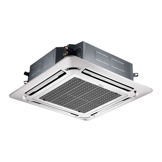
CASSETTE-TYPE AIR CONDITIONER
Installation Manual
Super-Slim Four-Way Cassette
MCD-18FNXD0 MOU-18FN8-QD0
MCD-24FNXD0 MOU-24FN8-QD0
MCD-36FNXD0 MOU-36FN8-QD0
MCD-36FNXD0
MOU-36FN8-RD0
MCD-48FNXD0 MOU-48FN8-RD0
MCD-55FNXD0 MOU-55FN8-RD0
IMPORTANT NOTE:
Read this manual carefully before
installing or operating your new air
conditioning unit. Make sure to save
this manual for future reference.
Advertisement
Table of Contents

Related Manuals for Midea MOU-18FN8-QD0


Summary of Contents for Midea MOU-18FN8-QD0
- Page 1 CASSETTE-TYPE AIR CONDITIONER Installation Manual Super-Slim Four-Way Cassette MCD-18FNXD0 MOU-18FN8-QD0 MCD-24FNXD0 MOU-24FN8-QD0 MCD-36FNXD0 MOU-36FN8-QD0 MCD-36FNXD0 MOU-36FN8-RD0 MCD-48FNXD0 MOU-48FN8-RD0 MCD-55FNXD0 MOU-55FN8-RD0 IMPORTANT NOTE: Read this manual carefully before installing or operating your new air conditioning unit. Make sure to save this manual for future reference.
-
Page 2: Table Of Contents
Table of Contents Installation Manual Accessories ............ Safety Precautions ........Installation Overview ....... Indoor Unit Installation Indoor Unit Installation ............Indoor Unit Parts ......... Indoor Unit Installation Instructions ..10 Outdoor Unit Installation ......Outdoor Unit Installation Instructions ..13 Drain Joint Installation ........ - Page 3 Refrigerant Piping Connection ....... Notes on Pipe Length and Elevation ....18 Refrigerant Piping Connection Instructions ...20 Wiring ..........Outdoor Unit Wiring ....Indoor Unit Wiring ...... Power Specifications ....Air Evacuation ..........Evacuation Instructions ........ Note on Adding Refrigerant .......
-
Page 4: Accessories
Accessories The air conditioning system comes with the following accessories. Use all of the installation parts and accessories to install the air conditioner. Improper installation may result in water leakage, electrical shock and fire, or cause the equipment to fail. Name Shape Quantity... -
Page 5: Safety Precautions
Safety Precautions Read Safety Precautions Before Installation Incorrect installation due to ignoring instructions can cause serious damage or injury. The seriousness of potential damage or injuries is classified as either a WARNING or CAUTION. Failure to observe a warning may result in death. The appliance must be installed in accordance with national regulations. - Page 6 WARNING The appliance disconnection must be incorporated with an all-pole disconnection device in the • xed wiring in accordance with the wiring rules. Any person who is involved with working on or breaking into a refrigerant circuit should hold a •...
- Page 7 Note about Fluorinated Gasses 1. This air-conditioning unit contains fluorinated gasses. For specific information on the type of gas and the amount, please refer to the relevant label on the unit itself. 2. Installation, service, maintenance and repair of this unit must be performed by a certified technician. 3.
-
Page 8: Installation Overview
Installation Overview INSTALLATION ORDER Install the indoor unit Install the outdoor unit Install the drainpipe (Page 9) (Page 12) (Page 15) Connect the wires Connect the refrigerant pipes Evacuate the refrigeration system (Page 25) (Page 22) (Page 19) Install the front panel Perform a test run (Page 27) (Page 29) - Page 9 Indoor Unit Installation Indoor Unit Parts Drain pump (within indoor unit) Drain pipe Air outlet Air inlet Front grille Louver Display panel Refrigerant pipe Fig. 4.1 Safety Precautions CAUTION WARNING • Securely install the indoor unit on a • Install the indoor and outdoor units, cables, structure that can sustain its weight.
- Page 10 Indoor Unit Installation Instructions CAUTION NOTE: Panel installation should be done after DO NOT install the unit in the following piping and wiring. locations: In areas with oil drilling or fracking Step 1: Select installation location In coastal areas with high salt content in the air The indoor unit should be installed in a location that meets the following requirements: In areas with caustic gases in the air, such...
- Page 11 Step 2: Hang indoor unit. 1. Use the included paper template to cut a rectangular hole in the ceiling, leaving at least 1m (39”) on all sides. The cut hole size should be 4cm(1.6”) larger than the boby size(See Fig. 4.3). Be sure to mark the areas where ceiling hook holes will be drilled.
- Page 12 5. Mount the indoor unit. You will need two NOTE: Ensure that the indoor unit is level. The people to lift and secure it. Insert suspension unit is equipped with a built-in drain pump and bolts into the unit’ s hanging holes. Fasten oat switch.
-
Page 13: Outdoor Unit Installation
Outdoor Unit Installation The area must be free of combustible gases √ Outdoor Unit Installation Instructions and chemicals. √ The pipe length between the outdoor and Step 1: Select installation location. indoor unit may not exceed the maximum The outdoor unit should be installed in the allowable pipe length. - Page 14 Split Type Outdoor Unit Vertical Discharge Type Outdoor Unit (Refer to Fig 5.4, 5.5, 5.6, 5.10 and Table 5.1) (Refer to Fig 5.7, 5.8, 5.9 and Table 5.2) (Wall or obstacle) Air Outlet >152.4cm / 60” Fig. 5.4 Fig. 5.7 Fig.
-
Page 15: Drain Joint Installation
NOTE: The minimum distance between the 2. Insert the drain joint into the hole in the base outdoor unit and walls described in the pan of the unit. installation guide does not apply to airtight 3. Rotate the drain joint 90° until it clicks in place rooms. - Page 16 Drainpipe Installation The drainpipe is used to drain water from the NOTE ON DRAINPIPE INSTALLATION unit. Improper installation may cause unit and When using an extended drainpipe, tighten • property damage. the indoor connection with an additional protection tube to prevent it from pulling CAUTION loose.
- Page 17 3. Using a 65-mm (2.5”) core drill, drill a hole in the wall. Make sure that the hole is drilled at a slight downward angle, so that the outdoor end of the hole is lower than the indoor end by about 12mm (0.5”). This will ensure proper water drainage (See Fig.
-
Page 18: Refrigerant Piping Connection
Refrigerant Piping Connection Safety Precautions Notes On Pipe Length and Elevation Ensure that the length of the refrigerant pipe, the number of bends, and the drop height between WARNING the indoor and outdoor units meets the • All eld piping must be completed by a requirements shown in Table 7.1: licensed technician and must comply with Table 7.1: The Maximum Length And Drop... - Page 19 CAUTION CAUTION • Oil traps If the outdoor unit is installed higher than the indoor unit: If the indoor unit is installed higher than the outdoor unit: -It is recommended that vertical suction risers not be upsized. Proper oil return to the -If oil flows back into the outdoor unit’s compressor should be maintained with suction compressor, this might cause liquid...
-
Page 20: Refrigerant Piping Connection Instructions
Table 7.2 Permitted length Total piping length 18K+18K 30/98’ L+Max 90° Oblique Rough Warped (L1, L2) 24K+24K 50/164’ 30K+30K Piping (farthest distance from 15/49’ L1, L2 length the line pipe branch) (farthest distance from 10/32.8’ L1-L2 the line pipe branch) Fig. - Page 21 4. Remove PVC tape from ends of pipe when 1. When connecting the flare nuts, apply a ready to perform flaring work. thin coat of refrigeration oil to the flared ends of the pipes. 5. Clamp flare form on the end of the pipe. 2.
- Page 22 NOTE ON MINIMUM BEND RADIUS Carefully bend the tubing in the middle according to the diagram below. DO NOT bend the tubing more than 90° or more than 3 times. Bend the pipe with thumb min-radius 10cm (3.9”) Fig. 7.12 6.
- Page 23 Wiring Follow these instructions to prevent distortion Safety Precautions when the compressor starts: • The unit must be connected to the main WARNING outlet. Normally, the power supply must • Be sure to disconnect the power supply have a low output impedance of 32 ohms. before working on the unit.
- Page 24 Table 8.2: Other Regions Indoor Unit Wiring Rated Current of Nominal Cross-Sectional 1. Prepare the cable for connection Appliance (A) Area (mm²) a. Using wire strippers, strip the rubber jacket from both ends of signal cable to reveal ≤ 6 0.75 about 15cm (5.9”) of the wires inside.
- Page 25 CAUTION While connecting the wires, please strictly follow the wiring diagram. • The refrigerant circuit can become very hot. Keep the interconnection cable away from • the copper tube. 5. Clamp down cable with the designated cable clamp to secure it in place. The cable should not be loose, and should not pull on the u-lugs.
- Page 26 Independent Power Supply Specifications ≤18K MODEL(Btu/h) 19K~24K 25K~36K 37K~48K 49K~60K PHASE 1 Phase 1 Phase 1 Phase 1 Phase 1 Phase POWER (indoor) 208-240V 208-240V 208-240V 208-240V 208-240V VOLT CIRCUIT BREAKER/ 15/10 15/10 15/10 15/10 15/10 FUSE(A) PHASE 1 Phase 1 Phase 1 Phase 1 Phase...
-
Page 27: Air Evacuation
Air Evacuation 4. Turn on the vacuum pump to evacuate the Safety Precautions system. 5. Run the vacuum for at least 15 minutes, or until the Compound Meter reads -76cmHG CAUTION (-1x10⁵Pa). • Use a vacuum pump with a gauge reading 6. -
Page 28: Note On Adding Refrigerant
Note On Adding Refrigerant CAUTION • Refrigerant charging must be performed after wiring, vacuuming and the leak test. DO NOT exceed the maximum allowable quantity of refrigerant or overcharge the system. • Doing so can damage or impact the unit’ s function. •... -
Page 29: Panel Installation
Panel Installation Step 3: Install the panel CAUTION Align the front panel to the main body, taking into account the position of the piping and DO NOT place the panel facedown on the floor, drain sides. Hang the four latches of the against a wall, or on uneven surfaces. - Page 30 2. Remove foam stops from inside the fan. 5. Close the front grille. 3. Attach the side of the front grille to the 6. Fasten the installation covers at all four panel. corners by pushing them inwards. (See Fig.10.6) 4. Connect the display panel cable to the corresponding wire on the main body.
-
Page 31: Test Run
Test Run f. Check to see that the drainage system is Before Test Run unimpeded and draining smoothly. A test run must be performed after the entire g. Ensure there is no vibration or abnormal system has been completely installed. Confirm noise during operation. -
Page 32: European Disposal Guidelines
European Disposal Guidelines Users in European Countries may be required to properly dispose of this unit. This appliance contains refrigerant and other potentially hazardous materials. When disposing of this appliance, the law requires special collection and treatment. DO NOT dispose of this product as household waste or unsorted municipal waste. -
Page 33: Impedance Information
Impedance Information (Applicable to Middle East Countries only) NOTE: To be in compliance with EN61000-3-11, the product MCDT4-36CRN1-QC5W shall be connected only to a supply of the system impedance: Zsys = 0.020 or less. Before connecting the product to public power network, please consult your local power supply authority to ensure the power network meet above requirement. -
Page 34: Information Servicing
Information Servicing (Required for the units adopt R32/R290 Refrigerant only) 1. Checks to the area Prior to beginning work on systems containing flammable refrigerants, safety checks are necessary to ensure that the risk of ignition is minimised. For repair to the refrigerating system, the following precautions shall be complied with prior to conducting work on the system. - Page 35 the charge size is in accordance with the room size within which the refrigerant containing parts are installed; the ventilation machinery and outlets are operating adequately and are not obstructed; if an indirect refrigerating circuit is being used, the secondary circuits shall be checked for the presence of refrigerant;...
- Page 36 11. Repair to intrinsically safe components Do not apply any permanent inductive or capacitance loads to the circuit without ensuring that this will not exceed the permissible voltage and current permitted for the equipment in use. Intrinscially safe components are the only types that can be worked on while live in the presence of a flammable atmosphere.
- Page 37 When the final OFN charge is used, the system shall be vented down to atmospheric pressure to enable work to take place. This operation is absolutely vital if brazing operations on the pipe-work are to take place. Ensure that the outlet for the vacuum pump is not closed to any ignition sources and there is ventilation available.
- Page 38 18. Labelling Equipment shall be labelled stating that it has been de-commissioned and emptied of refrigerant. The label shall be dated and signed. Ensure that there are labels on the equipment stating the equipment contains flammable refrigerant. 19. Recovery When removing refrigerant from a system, either for service or decommissioning, it is recommended good practice that all refrigerants are removed safely.
- Page 40 The design and specifications are subject to change without prior notice for product improvement. Consult with the sales agency or manufacturer for details. Please check the applicable models, F-GAS and manufacturer information from the Owner's Manual - Product Fiche in the packaging of the outdoor unit.
Need help?
Do you have a question about the MOU-18FN8-QD0 and is the answer not in the manual?
Questions and answers