Table of Contents
Advertisement
Quick Links
PS-2ADP Series
Low Air Differential Pressure Transmitters, Nema 4X
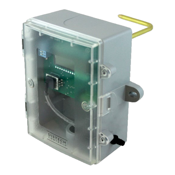
Figure 1a: PS-2ADP Series (-P models)
Product Description
The PS-2ADP Series transmitters can be used to measure positive, negative or differential pressure in ranges from 1 "WC to 40 "WC
(250 to 2000Pa). The piezoresistive sensor is ideal for monitoring the pressure of air or other clean inert gases and is limited only
to those media which will not attack polyetherimide, silicon, fluorosilicone, silicone, EPDM, and neoprene seals.
The PS-2ADP Series features field-selectable pressure ranges and output signal types for the most flexible applications. Typical
HVAC applications include monitoring of filter differential pressure or VAV applications. The output signal is factory calibrated and
temperature compensated for highest startup accuracy and trouble-free operation.
General Installation Requirements
For proper installation and subsequent operation of each device, pay special attention to the following recommendations:
-
Upon unpacking the product, inspect the contents of the carton for shipping damages. Do not install damaged device.
-
Avoid areas where corroding, deteriorating or explosive vapors, fumes or gases may be present.
-
Ensure that all equipment is installed according to local, regional, and national regulations.
Personal injury or loss of life may occur if you do not follow a procedure as specified.
Equipment damage or loss of data may occur if you do not follow a procedure as specified.
Do not use in an explosive or hazardous environment, with combustible or flammable gasses, as safety or emergency
stop devices or in any other application where failure of the product could result in personal injury
Take reasonable precautions to prevent electrostatic discharges to the controller when installing, servicing or operating
the controller. Discharge accumulated static electricity by touching one's hand to a well-grounded object before working
with the controller.
H a r d w a r e I n s t a l l a t i o n G u i d e
Figure 2b: PS-2ADP Series (-X models)
Advertisement
Table of Contents

Subscribe to Our Youtube Channel
Related Manuals for Greystone Energy Systems PS-2ADP Series


Summary of Contents for Greystone Energy Systems PS-2ADP Series
- Page 1 Product Description The PS-2ADP Series transmitters can be used to measure positive, negative or differential pressure in ranges from 1 “WC to 40 “WC (250 to 2000Pa). The piezoresistive sensor is ideal for monitoring the pressure of air or other clean inert gases and is limited only to those media which will not attack polyetherimide, silicon, fluorosilicone, silicone, EPDM, and neoprene seals.
- Page 2 Mounting Instructions The transducer mounts on a vertical surface using the two integrated mounting holes. Ensure there is enough space around the unit to connect the pressure tubing without kinking and to make the electrical connections, avoid locations with severe vibrations or excessive moisture.
- Page 3 Figure 5b: Closing (-X models) Figure 5a: Closing (-P models) Wiring The transmitter has standard screw block connectors and easy wire access to facilitate wiring. It is recommended that shielded twisted pair wiring at least 22 AWG be used for all connections and that the device wires not be run in the same conduit with wiring used to supply inductive loads such as motors.
- Page 4 Figure 6b: Wiring (-X models) Configuration The transmitter is configured with switches located on the circuit board as shown on the PCB drawing. These switches are used to select the output signal type and the input pressure range. The unit is factory configured to operate in the 4-20 mA output mode. This can be changed to the voltage mode by moving the switch from the position marked 4-20 mA to the position marked Voltage.
- Page 5 Pneumatic Connections The two pressure ports on the end of the enclosure are labeled High and Low. The output signal reads a positive value when the port pressure is higher on the High port than the Low port so ensure these ports are connected correctly. Use 0.170” I.D. flexible tubing for the pressure connections.
- Page 6 Specifications Pressure Ranges ±4", ±2", ±1", 0-4", 0-2", 0-1 “WC ±8", ±5", 0-8", 0-5", 0-3 “WC ±12", ±10", ±6", 0-12", 0-10", 0-6 “WC ±20", ±15", ±10", 0-20", 0-15", 0-10 “WC ±1000 Pa, ±500 Pa, ±250 Pa, 0-1000 Pa, 0-5000 Pa, 0-250 Pa ±2000 Pa, ±1000 Pa, ±500 Pa, 0-2000 Pa, 0-1000 Pa, 0-500 Pa (6 per model, switch selectable) Accuracy...
- Page 7 Dimensions Figure 7a: Dimensions (-P models)
- Page 8 Figure 7b: Dimensions (-X models) ©, Distech Controls Inc. 2023 All rights reserved. While all efforts have been made to verify the accuracy of information in this manual, Distech Controls is not responsible for damages or claims arising from the use of this manual. Persons using this manual are assumed to be trained HVAC specialist / installers and are responsible for using the correct wiring procedures and maintaining safe working conditions with fail-safe environments.
Need help?
Do you have a question about the PS-2ADP Series and is the answer not in the manual?
Questions and answers