Table of Contents
Advertisement
Quick Links
BEFORE INSTALLATION
Read these instructions carefully before installing and commissioning the gas sensor. Failure to follow
these instructions may result in product damage. Do not use this device in an explosive or hazardous
environment, with combustible or flammable gases, as a safety or emergency stop device or in any other
application where failure of the product could result in personal injury. Follow electronic discharge
precautions during installation and do not exceed the device ratings.
MOUNTING
For wall mounting, select a suitable mounting
area away from opening windows or doors and
avoid areas subject to high vibrations or excessive
moisture. The recommended mounting height is
1.2 - 1.8 m (4' - 6') above the floor. The enclosure
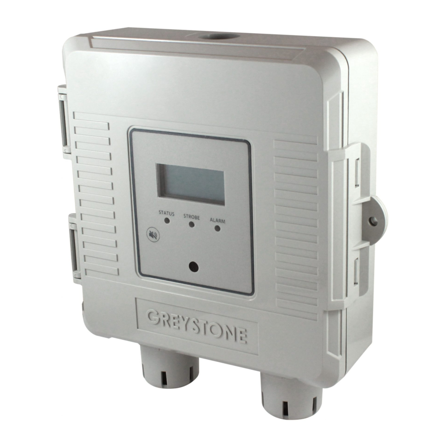
has a hinged cover with a latch. Open the cover
by pulling slightly on the latch on the right side
of the enclosure as shown in Figure 1. Mount the
device directly to the flat surface using the four
integrated mounting holes that are provided on
each corner of the enclosure using screws (not
provided). Ensure the sensor pods are pointing
downwards as shown in Figure 1.
The enclosure offers two entry points for wiring
one on top and one on bottom, see Figure 2 for
locations. The enclosure includes one rubber
grommet installed in the bottom wiring hole.
Depending on the installation wiring can be routed
through top or bottom hole and the grommet can
be placed in the unused hole. The hole provided
is for conduit or cable gland mounting. The hole
size is 21.38mm (0.86") diameter.
Make wiring connections as per the "Wiring"
illustrations as shown in Figure 6. Once the wiring
and device setup are complete, close and latch
the cover. The enclosure includes a hole to allow
the use of anti-tamper device.
REMOTE NO
MOUNTING
2
The recommended mounting height for the
remote NO2 sensor is 0.6 m (2') below the ceiling
and must be mounted within 3m (10') of the
main enclosure as shown in Figure 3. Secure the
enclosure to the selected section of wall above the main enclosure with (2) #10 x 25 mm (1") self-tapping
screws (not provided) and tighten screws until the enclosure is tight against the wall as shown in Figure 4.
Ensure there is no movement of the enclosure.
IN-GE-GDTXXX-06
Copyright © Greystone Energy Systems, Inc. All Rights Reserved Phone: +1 506 853 3057 Web: www.greystoneenergy.com
Carbon Monoxide/Nitrogen
INTRODUCTION
The Carbon Monoxide/Nitrogen Dioxide series of sensors
monitor CO gas levels and offers an optional local or
remote NO
sensor.
2
Features include an LCD for configuration and monitoring,
various output signal types, optional temperature sensor,
optional relays for alarm indication, optional high intensity
strobe and buzzer for alarms and field replaceable
calibrated sensors.
Figure 1
Figure 2
Figure 3
Maximum Distance
Dioxide Transmitter
GDT Series - Installation Instructions
Recommended Mounting
Height
1.2 - 1.8m (4 - 6')
Wiring entry
Sensor Pods
Figure 4
3m (10')
Page 1
Advertisement
Table of Contents

Related Manuals for Greystone Energy Systems GDT Series


Summary of Contents for Greystone Energy Systems GDT Series
- Page 1 (not provided) and tighten screws until the enclosure is tight against the wall as shown in Figure 4. Ensure there is no movement of the enclosure. IN-GE-GDTXXX-06 Copyright © Greystone Energy Systems, Inc. All Rights Reserved Phone: +1 506 853 3057 Web: www.greystoneenergy.com Page 1...
- Page 2 COMMON Analog Input 24 Vac TEMP Analog Input COMMON Analog Input Controller COMMON Analog Input Analog Input TEMP Analog Input Controller IN-GE-GDTXXX-06 Copyright © Greystone Energy Systems, Inc. All Rights Reserved Phone: +1 506 853 3057 Web: www.greystoneenergy.com Page 2...
- Page 3 Do not exceed the device contact ratings. In some cases, a separate control relay may be used between the sensor relay and a large fan for example. IN-GE-GDTXXX-06 Copyright © Greystone Energy Systems, Inc. All Rights Reserved Phone: +1 506 853 3057 Web: www.greystoneenergy.com Page 3...
-
Page 4: Operation - Start-Up
0-300 ppm CO or 0-10 ppm NO IN-GE-GDTXXX-06 Copyright © Greystone Energy Systems, Inc. All Rights Reserved Phone: +1 506 853 3057 Web: www.greystoneenergy.com Page 4... -
Page 5: Operation - Alarms
For a CO buzzer alarm, the sound is a short beep • For an NO buzzer alarm, the sound is a long beep IN-GE-GDTXXX-06 Copyright © Greystone Energy Systems, Inc. All Rights Reserved Phone: +1 506 853 3057 Web: www.greystoneenergy.com Page 5... -
Page 6: Manual Alarm Reset
Test time can be programmed via the menu. The Test Mode display will show even if the LCD mode is set to off. TestMode TestMode 300 Sec 299 Sec IN-GE-GDTXXX-06 Copyright © Greystone Energy Systems, Inc. All Rights Reserved Phone: +1 506 853 3057 Web: www.greystoneenergy.com Page 6... -
Page 7: Operation - Setup Menu
0-100ppm, 0-150ppm, 0-300pm, 0-400ppm, or 0-500ppm. The 0-300ppm factory default CO range is 0-300ppm. <MENU> Press to advance to next menu item IN-GE-GDTXXX-06 Copyright © Greystone Energy Systems, Inc. All Rights Reserved Phone: +1 506 853 3057 Web: www.greystoneenergy.com Page 7... - Page 8 Press the <UP> or <DOWN> to toggle the buzzer ON or OFF. Test OFF <MENU> Press to advance to next menu item IN-GE-GDTXXX-06 Copyright © Greystone Energy Systems, Inc. All Rights Reserved Phone: +1 506 853 3057 Web: www.greystoneenergy.com Page 8...
- Page 9 The available options are CO or NO . Alarm1 may be assigned to either sensor. The default is CO. <MENU> Press to advance to next menu item IN-GE-GDTXXX-06 Copyright © Greystone Energy Systems, Inc. All Rights Reserved Phone: +1 506 853 3057 Web: www.greystoneenergy.com Page 9...
-
Page 10: Relay Operation
1 to 10 ppm in 1 ppm increments. Default is 4 ppm. Trip 4 <MENU> Press to advance to next menu item IN-GE-GDTXXX-06 Copyright © Greystone Energy Systems, Inc. All Rights Reserved Phone: +1 506 853 3057 Web: www.greystoneenergy.com Page 10... - Page 11 TEST switch is pressed. <MENU> Press to advance to next menu item IN-GE-GDTXXX-06 Copyright © Greystone Energy Systems, Inc. All Rights Reserved Phone: +1 506 853 3057 Web: www.greystoneenergy.com Page 11...
- Page 12 If the CO sensor is calibrated with gas via the User Menu then the timer will be automatically reset. IN-GE-GDTXXX-06 Copyright © Greystone Energy Systems, Inc. All Rights Reserved Phone: +1 506 853 3057 Web: www.greystoneenergy.com Page 12...
-
Page 13: Alarm Mode
0-0.5 ppm. The factory NO2 ON default is ON. Note that the zero filter is automatically disabled when performing a NO gas calibration. IN-GE-GDTXXX-06 Copyright © Greystone Energy Systems, Inc. All Rights Reserved Phone: +1 506 853 3057 Web: www.greystoneenergy.com Page 13... - Page 14 The default BACnet address is 3. Each device on the network 40. ADDRESS MAC 3 must have a unique address. <MENU> Press to advance to next menu item IN-GE-GDTXXX-06 Copyright © Greystone Energy Systems, Inc. All Rights Reserved Phone: +1 506 853 3057 Web: www.greystoneenergy.com Page 14...
-
Page 15: Zero Calibration
Counter is incremented every time this step is performed. The Cal DONE CO Re-Cal timer is reset whenever this step is performed. <MENU> Press to advance to next menu item IN-GE-GDTXXX-06 Copyright © Greystone Energy Systems, Inc. All Rights Reserved Phone: +1 506 853 3057 Web: www.greystoneenergy.com Page 15... - Page 16 -5.0 to +5.0 for °C and -10.0 to +10.0 for °F. Resolution is 0.1°. <MENU> Press to exit the Setup Menu and return to normal mode IN-GE-GDTXXX-06 Copyright © Greystone Energy Systems, Inc. All Rights Reserved Phone: +1 506 853 3057 Web: www.greystoneenergy.com Page 16...
-
Page 17: Specifications
Wiring Connections ........Screw terminal block (14 to 22 AWG) Top or bottom conduit entry 22.73 mm (0.875") hole Approvals ............CE Country of Origin ..........Canada IN-GE-GDTXXX-06 Copyright © Greystone Energy Systems, Inc. All Rights Reserved Phone: +1 506 853 3057 Web: www.greystoneenergy.com Page 17... -
Page 18: Bacnet® Protocol
BACnet® and Modbus setup guide downloads are available online. BACnet® PROTOCOL https://downloads.greystoneenergy.com/SG/SG-GDTXXXBAC-003.pdf MODBUS PROTOCOL https://downloads.greystoneenergy.com/SG/SG-GDTXXXMOD-001.pdf Page 18 IN-GE-GDTXXX-06 Copyright © Greystone Energy Systems, Inc. All Rights Reserved Phone: +1 506 853 3057 Web: www.greystoneenergy.com...
Need help?
Do you have a question about the GDT Series and is the answer not in the manual?
Questions and answers