Advertisement
Table of Contents
BEFORE INSTALLATION
Read these instructions carefully before installing and commissioning the CO transmitter. Failure to follow
these instructions may result in product damage. Do not use in an explosive or hazardous environment,
with combustible or flammable gases, as a safety or emergency stop device or in any other application
where failure of the product could result in personal injury. Take electrostatic discharge precautions
during installation and do not exceed the device ratings.
MOUNTING
The device should be mounted five feet from the floor of the area to be controlled. The four integrated
mounting holes facilitate a #10 size screw (not supplied). See Figure 1. Do not mount the sensor near doors,
opening windows, supply air diffusers, or any other known air disturbances. Avoid areas with vibrations
or rapid temperature changes.
The enclosure has a hinged cover with a latch, open it by pulling slightly on the latch on the right side of
the enclosure while pulling on the cover. See Figure 2.
Make all connections as per the "Wiring" instructions on page 2.
Once all connections are complete, latch the cover. Two self-taping screws are provided for extra security,
see Figure 3.
HARDWARE SETUP
The only hardware setup required is to select the
analog output type with the PCB switch labeled
VOLT and mA. Slide the switch to the correct
position for the required output signal type, either
4-20 mA or 0-5/10 Vdc.
Figure 2
IN-GE-CMD5B4XXX-01-02
03/19
Copyright © Greystone Energy Systems, Inc. All Rights Reserved Phone: +1 506 853 3057 Web: www.greystoneenergy.com
Carbon Monoxide Transmitter
CMD5B4 Series - Installation Instructions
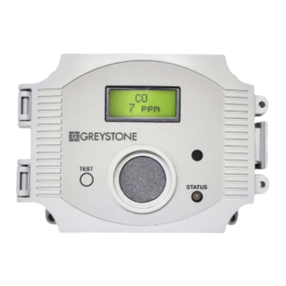
INTRODUCTION
The Carbon Monoxide Transmitter uses an electrochemical
sensor to monitor th carbon monoxide level and outputs
a field-selectable 4-20 mA or voltage signal. The voltage
signal may also be set to 0-5 or 0-10 Vdc. The sensing range
and output may be scaled to either 100, 150, 300, 400,
or 500 ppm via the on-board menu. A front panel LCD is
standard to ensure easy setup and operation.
Other standard features include a back light for the LCD,
a front panel test switch, status indication and an alarm
buzzer. The text function may also be controlled remotely
with a digital input signal. A three-key menu is implemented
to allow local configuration of all device parameters.
Figure 1
Figure 3
Page 1
Advertisement
Table of Contents

Related Manuals for Greystone Energy Systems CMD5B4 Series


Summary of Contents for Greystone Energy Systems CMD5B4 Series
- Page 1 VOLT and mA. Slide the switch to the correct position for the required output signal type, either 4-20 mA or 0-5/10 Vdc. Figure 2 Figure 3 IN-GE-CMD5B4XXX-01-02 03/19 Copyright © Greystone Energy Systems, Inc. All Rights Reserved Phone: +1 506 853 3057 Web: www.greystoneenergy.com Page 1...
- Page 2 TEST switch. The Test function may also be initiated remotely by shorting the Figure 4 IN-GE-CMD5B4XXX-01-02 03/19 Copyright © Greystone Energy Systems, Inc. All Rights Reserved Phone: +1 506 853 3057 Web: www.greystoneenergy.com Page 2...
-
Page 3: Manual Alarm Reset
TEST input). If the CO level is below the alarm level AND the TEST switch is pressed, then the relay alarms will return to the Normal Mode. IN-GE-CMD5B4XXX-01-02 03/19 Copyright © Greystone Energy Systems, Inc. All Rights Reserved Phone: +1 506 853 3057 Web: www.greystoneenergy.com Page 3... - Page 4 0-300ppm 0-400ppm, or 0-500ppm Press the <SAVE> key to save any change. <MENU> Press to advance to next menu item IN-GE-CMD5B4XXX-01-02 03/19 Copyright © Greystone Energy Systems, Inc. All Rights Reserved Phone: +1 506 853 3057 Web: www.greystoneenergy.com Page 4...
-
Page 5: Buzzer Alarm
Press to advance to next menu item Relay 1 10. ON/OFF Use the <ROLL> key to toggle relay 1 ON or OFF. Test OFF IN-GE-CMD5B4XXX-01-02 03/19 Copyright © Greystone Energy Systems, Inc. All Rights Reserved Phone: +1 506 853 3057 Web: www.greystoneenergy.com Page 5... -
Page 6: Operating Time
This item sets how long the test mode will operate when the TEST switch is pressed. <MENU> Press to advance to next menu item IN-GE-CMD5B4XXX-01-02 03/19 Copyright © Greystone Energy Systems, Inc. All Rights Reserved Phone: +1 506 853 3057 Web: www.greystoneenergy.com Page 6... - Page 7 ZERO gas calibration. <MENU> Press to advance to next menu item IN-GE-CMD5B4XXX-01-02 03/19 Copyright © Greystone Energy Systems, Inc. All Rights Reserved Phone: +1 506 853 3057 Web: www.greystoneenergy.com Page 7...
- Page 8 0 ppm. The ZERO and SPAN pots are located on the edge of the cover sensor PCB and are clearly marked on the PCB. IN-GE-CMD5B4XXX-01-02 03/19 Copyright © Greystone Energy Systems, Inc. All Rights Reserved Phone: +1 506 853 3057 Web: www.greystoneenergy.com Page 8...
-
Page 9: Specifications
) or 15 m (50 ft) radius Wiring Connections ...Screw terminal block (14 to 22 AWG) Country of Origin ....Canada DIMENSIONS Page 9 IN-GE-CMD5B4XXX-01-02 03/19 Copyright © Greystone Energy Systems, Inc. All Rights Reserved Phone: +1 506 853 3057 Web: www.greystoneenergy.com...
Need help?
Do you have a question about the CMD5B4 Series and is the answer not in the manual?
Questions and answers