Table of Contents
Advertisement
Quick Links
Standard features include a field selectable output signal of either 4-20 mA, 0-5 Vdc or 0-10 Vdc for the
highest versatility, programmable CO
operation for configuration.
Optional features include a resistive temperature sensor output (with LCD display of temperature in
either °C or °F), a control relay with programmable setpoint, hysteresis and time delay, and either a
conduit or cable gland connection point.
BEFORE INSTALLATION
Read these instructions carefully before installing and commissioning the device. Failure to follow these
instructions may result in product damage. Do not use in an explosive or hazardous environment, with
combustible or flammable gases, as a safety or emergency stop device or in any other application where
failure of the product could result in personal injury. Take electrostatic discharge precautions during
installation. De-energize the power supply prior to installation, this device is intended for indoor air
conditioned spaces, contact factory or other applications. Do not exceed device ratings. This product
is not intended for life-safety applications.
NOTE: This CO
sensor incorporates a Self Calibration feature to correct CO
2
recommended for applications where the CO
per day. If the monitored space is occupied 24 hours or consistently maintains higher or lower levels
of CO
, it is recommended that this feature be turned off, but yearly calibration will be required. If the
2
self calibration is disabled at installation time without allowing for 7 day auto calibration cycle, then a
manual calibration should be performed to ensure accuracy of the device.
MOUNTING
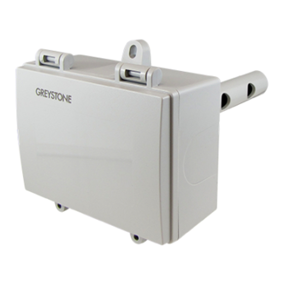
The duct type sensor installs on the outside of a return air duct with the sampling tube inserted into the
duct. Use the included foam plug to prevent air from entering the enclosure through the conduit and
causing an incorrect reading.
Mount the sensor in an easily accessible location in a straight section
of duct at least five feet from corners or other items that may cause
disturbances in the air flow. Avoid areas where the detector is exposed
to vibrations or rapid temperature changes.
The duct CO
detector principal of operation is based on the Venturi
2
effect of the probe that extends into the HVAC duct. Air flowing through
the duct is forced into the vent holes on one side of the probe, into
the enclosure, over the CO
enclosure via the probe vent holes on the opposite side.
NOTE: To ensure proper temperature readings, if present, the
temperature inlet on the probe must be installed directly into the
airflow. See Figure 1.
Figure 2
IN-GE-CD2DTXXX-03
INTRODUCTION
The duct CO
2
infrared (NDIR) sensor in an attractive enclosure with a gasketed, hinged
cover for duct applications to monitor CO
dual channel optics and LTA (long term adjustment) signal processing
technology to deliver industry leading long term accuracy and reliability.
These technology features ensure optimum measurement stability for
both periodic and constant occupancy applications so the device is
equally suitable for return-air measurement from the classroom or the
hospital room.
measurement span, a backlit alpha-numeric LCD and easy menu
2
sensor and then is drawn back out of the
2
Copyright © Greystone Energy Systems, Inc. All Rights Reserved Phone: +1 506 853 3057 Web: www.greystoneenergy.com
Duct Carbon Dioxide Transmitter
device uses a highly accurate and reliable non-dispersive
will be exposed to fresh air (400 ppm) at least one hour
2
Figure 3
EMT Connector
CD2DT Series - Installation Instructions
levels. The sensor uses
2
sensor drift. This feature is
2
Figure 1
Thread adapter and
cable gland fitting
Airflow
Page 1
Advertisement
Table of Contents

Related Manuals for Greystone Energy Systems CD2DT Series


Summary of Contents for Greystone Energy Systems CD2DT Series
- Page 1 See Figure 1. Figure 2 Figure 3 Thread adapter and cable gland fitting EMT Connector IN-GE-CD2DTXXX-03 Copyright © Greystone Energy Systems, Inc. All Rights Reserved Phone: +1 506 853 3057 Web: www.greystoneenergy.com Page 1...
- Page 2 (the signal current is generated by the transmitter and must not be connected to a powered input or device damage will result). Copyright © Greystone Energy Systems, Inc. All Rights Reserved Phone: +1 506 853 3057 Web: www.greystoneenergy.com Page 2...
- Page 3 “ON". If disabling this feature a manual calibration should be performed to ensure accuracy of the device. <MENU> Press to advance to next menu item Copyright © Greystone Energy Systems, Inc. All Rights Reserved Phone: +1 506 853 3057 Web: www.greystoneenergy.com Page 3 IN-GE-CD2DTXXX-03...
- Page 4 1235 ppm 24.3 °C None No measurement information is displayed in normal mode, the menu will still display in Setup Menu mode Copyright © Greystone Energy Systems, Inc. All Rights Reserved Phone: +1 506 853 3057 Web: www.greystoneenergy.com Page 4 IN-GE-CD2DTXXX-03...
- Page 5 RESOLUTION Temp High or Low 0.5°C/F 0.2 to 5.0°C/F 0.1°C/F High or Low 50 ppm 25 to 500 ppm 25 ppm Copyright © Greystone Energy Systems, Inc. All Rights Reserved Phone: +1 506 853 3057 Web: www.greystoneenergy.com Page 5 IN-GE-CD2DTXXX-03...
- Page 6 / Done” if the process was successful. If “Calibrat / Fail” is displayed then the process may have to be repeated. Press the <MENU> key to return to normal operation, shut off the gas supply and remove the sensor adapter. Copyright © Greystone Energy Systems, Inc. All Rights Reserved Phone: +1 506 853 3057 Web: www.greystoneenergy.com Page 6 IN-GE-CD2DTXXX-03...
- Page 7 DIMENSIONS 53.7 mm 116.5 mm 2.11" 4.58" 152 mm 6" 112.5 mm 22.5 mm 99.7 mm 4.43" 0.88" 3.93" 0.5" NPT Page 7 Copyright © Greystone Energy Systems, Inc. All Rights Reserved Phone: +1 506 853 3057 Web: www.greystoneenergy.com IN-GE-CD2DTXXX-03...
Need help?
Do you have a question about the CD2DT Series and is the answer not in the manual?
Questions and answers