Table of Contents
Advertisement
Quick Links
BEFORE INSTALLATION
Read these instructions carefully before installing and commissioning the device. Failure to follow these
instructions may result in product damage. Do not use in an explosive or hazardous environment, with
combustible or flammable gases, as a safety or emergency stop device or in any other application where
failure of the product could result in personal injury. Take electrostatic discharge precautions during
installation. Do not exceed device ratings.
MOUNTING
The transmitter installs directly on a standard electrical box and should be mounted five feet from the floor
of the area to be controlled. Do not mount the sensor near doors, opening windows, supply air diffusers or
other known disturbances. Avoid areas where the detector is exposed to vibrations or rapid temperature
changes.
The cover is hooked to the base at the top edge and must be removed from the bottom edge first. Use a small
Phillips screwdriver to loosen the security screw as shown in Figure 1.
Complete removal of the screw is not required. Use the screwdriver to
carefully pry each bottom corner if necessary. Tip the cover away from
the base and sit it aside as shown in Figure 2.
Sit the PCB aside until the base is mounted on the wall. For added
protection, place the PCB in the supplied anti-static bag.
Mount the base by screwing to an electrical box or directly to the wall
as shown in Figure 4. The mounting hole locations are shown on page
4.
After the base is screwed to an electrical box or directly to the wall
using the appropriate holes, remove the PCB from the anti-static bag,
feed connection wires through the center hole and place the top of
the PCB into the PCB holders on the backplate and snap the bottom of
the PCB into place as shown in Figure 4.
Making wiring connections as per the Wiring Illustrations on page 2
and install the decorative cover by placing the top of the cover into
the cover holder on the top of the backplate and snapping the bottom
into place as shown in Figure 4. Tighten the security screw with a
Phillips screwdriver.
Figure 3
IN-GE-CDD3B1XXXMOD-01-03
11/19 Copyright © Greystone Energy Systems, Inc. All Rights Reserved Phone: +1 506 853 3057 Web: www.greystoneenergy.com
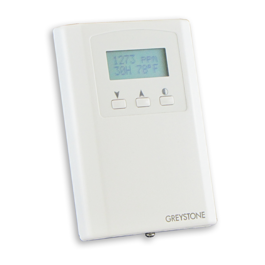
INTRODUCTION
The carbon dioxide transmitter uses Infrared Technology to monitor
CO
levels within a range of 0 - 2000 ppm. Options include a control
2
relay, override switch, up/down set-point control, relative humidity
sensor and temperature sensor.
The device includes Modbus protocol with 16 I/O registers and an
RS-485 MS/TP network connection to offer a single-point solution
for control of indoor air quality and comfort. Features include a
back-lit LCD and user menu for easy installation, field-proven RH
sensor and user input controls to add local set-point and override
functions at the same network point.
Figure 4
Cover
Room Carbon Dioxide
Transmitter with Modbus
CDD3B1 Series - Installation Instructions
Figure 1
Figure 2
PCB
Backplate
Page 1
Advertisement
Table of Contents

Subscribe to Our Youtube Channel
Related Manuals for Greystone Energy Systems CDD3B1 Series


Summary of Contents for Greystone Energy Systems CDD3B1 Series
- Page 1 Figure 4. Tighten the security screw with a Phillips screwdriver. Figure 4 Figure 3 Cover Backplate IN-GE-CDD3B1XXXMOD-01-03 11/19 Copyright © Greystone Energy Systems, Inc. All Rights Reserved Phone: +1 506 853 3057 Web: www.greystoneenergy.com Page 1...
- Page 2 LCD. The sensor operates on a 4 second interval and will update the output and display every 4 seconds. IN-GE-CDD3B1XXXMOD-01-03 11/19 Copyright © Greystone Energy Systems, Inc. All Rights Reserved Phone: +1 506 853 3057 Web: www.greystoneenergy.com Page 2...
- Page 3 E (even). Press the save key to save the change. Parity N <MENU> Press to advance to next menu item IN-GE-CDD3B1XXXMOD-01-03 11/19 Copyright © Greystone Energy Systems, Inc. All Rights Reserved Phone: +1 506 853 3057 Web: www.greystoneenergy.com Page 3...
- Page 4 60 to 80°F setpoint (1°F steps) <SAVE> Press to exit the menu and return to normal operation or <MENU> to repeat the menu. IN-GE-CDD3B1XXXMOD-01-03 11/19 Copyright © Greystone Energy Systems, Inc. All Rights Reserved Phone: +1 506 853 3057 Web: www.greystoneenergy.com Page 4...
- Page 5 Done. Press the <SAVE> key to return to normal operation and then the gas can be shut off. Disconnect the tubing and replace the cap on the sensor chamber as calibration is complete. IN-GE-CDD3B1XXXMOD-01-03 11/19 Copyright © Greystone Energy Systems, Inc. All Rights Reserved Phone: +1 506 853 3057 Web: www.greystoneenergy.com Page 5...
- Page 6 Country of Origin ......Canada DIMENSIONS 58 mm 29 mm 84 mm 2.3 “ 1.15 “ 3.3“ 119 mm 82.6 mm 4.7“ 3.25 “ IN-GE-CDD3B1XXXMOD-01-03 11/19 Copyright © Greystone Energy Systems, Inc. All Rights Reserved Phone: +1 506 853 3057 Web: www.greystoneenergy.com Page 6...
- Page 7 Modbus setup guide download is available online. MODBUS PROTOCOL https://downloads.greystoneenergy.com/SG/SG-CDD3B1XXXMOD.pdf Page 7 IN-GE-CDD3B1XXXMOD-01-03 11/19 Copyright © Greystone Energy Systems, Inc. All Rights Reserved Phone: +1 506 853 3057 Web: www.greystoneenergy.com...
Need help?
Do you have a question about the CDD3B1 Series and is the answer not in the manual?
Questions and answers