York Champion Series Technical Manual
Single package heat pumps
Hide thumbs
Also See for Champion Series:
- Installation instructions manual (28 pages) ,
- Installation instructions manual (18 pages)
Table of Contents
Advertisement
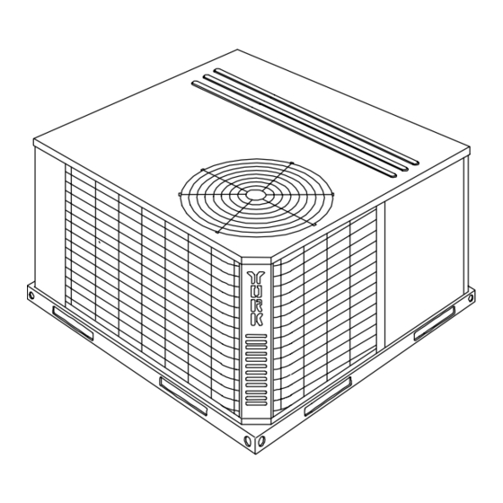
DESCRIPTION
These packaged heat pumps are designed for outdoor instal-
lation. Only utility and duct connections are required at the
point of installation.
Field-installed electric heater accessories are available to
provide electric heat, if required.
STANDARD FEATURES / BENEFITS
OPERATING EFFICIENCY - All units provide high operating
efficiencies of 10 SEER or greater, 3.0 COP or greater and up to
7.0 HSPF. All efficiencies exceed legislated minimum levels.
ON SITE FLEXIBILITY - All model sizes share a common,
compact design cabinet with a single footprint. The installer
has the flexibility of setting one curb or pad and placing the
proper tonnage unit on that curb after the internal load has
been determined. Field convertible duct connections from
side shot to down shot allows the installer to have greater
flexibility and needs to carry less inventory.
LOWER INSTALLATION COST - Installation time and costs
are reduced by easy power and control wiring connections.
The small base dimension means less space is required on
the ground or roof, plus, the installer can fit this unit between
the wheel wells of full size pick-up truck. All models are well
under 500 pounds.
All units are completely wired, charged with R-22 and tested
prior to shipment. Unique test stations using a new state of the
art computerized process system are used to insure product
quality. Refrigerant charge, and component part numbers are
verified via computers at manufacturing point. Vital run test sta-
FOR DISTRIBUTION USE ONLY - NOT TO BE USED AT POINT OF RETAIL SALE
TECHNICAL GUIDE
®
Champion Series
SINGLE PACKAGE
HEAT PUMPS
BHA018 THRU 060
1-1/2 THRU 5 NOMINAL TONS
10 SEER
tistics such as system pressure, motor currents, air velocity and
temperature and unit vibration are monitored and recorded by
the system to insure unit performance.
Equal size, side supply and return duct connections allows
easy hook-up of ducts to match low crawl spaces without tran-
sition pieces.
UTILITY CONNECTIONS MADE EASY - Electrical utility
knockouts are provided through the bottom as well as the side
of the unit. Utility connections can be made quickly and with a
minimum amount of field labor. A field supplied and field in-
stalled electrical disconnect switch must be installed.
CONVERTIBLE AIRFLOW DESIGN - The bottom duct open-
ings are covered when they leave the factory ready to be used
for a side supply / side return application. If a bottom supply / bot-
tom return application is desired, you simply remove the two
panels from the bottom of the unit and place them in the side
supply / side return duct openings. No panel cutting is required
and no accessory panel is necessary. Convertible airflow design
allows maximum field flexibility and minimum inventory.
CONDENSATE PAN - A non-corrosive, long-lasting, water-tight
pan is positioned below the evaporator coil to collect and drain all
condensate. Less collection of stagnate condensate will build-
up. The condensate pan conforms to ASHRAE 62-89 standards
(Ventilation for Acceptable Indoor Air Quality).
CONDENSATE DRAIN - The heavy duty,
connection is more tolerable during installation and is more
durable over time. The connection is rigidly mounted to as-
sure proper fit and leak tight seal.
036-21311-003-A-0104
®
!
inch NPTI copper
"
Advertisement
Table of Contents

Related Manuals for York Champion Series


Summary of Contents for York Champion Series
-
Page 1: Description
036-21311-003-A-0104 ® TECHNICAL GUIDE ® Champion Series SINGLE PACKAGE HEAT PUMPS BHA018 THRU 060 1-1/2 THRU 5 NOMINAL TONS 10 SEER DESCRIPTION tistics such as system pressure, motor currents, air velocity and These packaged heat pumps are designed for outdoor instal- temperature and unit vibration are monitored and recorded by lation. - Page 2 036-21311-003-A-0104 STANDARD FEATURES and BENEFITS - continued DURABLE FINISH - With a heavy duty cabinet made of FAN SYSTEM - All models operate over a wide range of design powder-painted, galvanized steel the neutral color blends into conditions with a 3-speed direct-drive fan motor. These units surrounding areas.
-
Page 3: Table Of Contents
036-21311-003-A-0104 FIELD-INSTALLED ACCESSORIES ECONOMIZER DOWN DISCHARGE / SUPPLY KIT - Modu- MOTORIZED FRESH AIR DAMPER - Designed for duct lating integrated economizer provides simultaneous opera- mounted side supply/return and unit mounted down sup- tion between the mechanical cooling and economizer ply/return applications. -
Page 4: Ratings
036-21311-003-A-0104 DIRECT DRIVE CONDENSER FAN MOTOR HIGHLY EFFICIENT ENHANCED COPPER TUBE/ALUMINUM FIN INDOOR COIL BACK AND BOTTOM HIGHLY EFFICIENT RETURN AIR ENHANCED COPPER AND SUPPLY AIR TUBE/ALUMINUM FIN DUCT OPENING OUTDOOR COIL DECORATIVE PROTECTIVE COIL GUARD HIGH VOLTAGE TERMINAL BLOCK LOW VOLTAGE TERMINAL BLOCK 3-SPEED DIRECT DRIVE... -
Page 5: Cooling Capacities - Bha018
036-21311-003-A-0104 COOLING CAPACITIES - 1-1/2 TON (BHA018) Air On Indoor Coil 450 CFM 525 CFM 600 CFM 675 CFM 750 CFM Temperature of Air on Outdoor Coil WB°F WB°F WB°F WB°F WB°F Net Cap 20.5 19.2 16.8 17.4 21.4 19.9 17.5 18.1 22.2 20.7 18.2 18.8 22.6 21.1 18.5 19.1 23.0 21.4 18.8 19.4 Total Power 1.84 1.81 1.80 1.79 1.87 1.84 1.83 1.81 1.89 1.87 1.86 1.84 1.92 1.89 1.88 1.86 1.94 1.92 1.90 1.89 Input kW... -
Page 6: Cooling Capacities - Bha024
036-21311-003-A-0104 COOLING CAPACITIES - 2 TON (BHA024) Air On Indoor Coil 600 CFM 700 CFM 800 CFM 900 CFM 1,000 CFM Temperature of Air on Outdoor Coil WB°F WB°F WB°F WB°F WB°F Net Cap 25.3 23.1 20.8 20.8 26.4 24.1 21.7 21.6 27.4 25.0 22.5 22.5 28.1 25.6 23.1 23.0 28.7 26.2 23.6 23.5 Total Power 2.21 2.18 2.14 2.12 2.26 2.23 2.18 2.16 2.30 2.27 2.22 2.20 2.33 2.30 2.25 2.22 2.35 2.32 2.27 2.25 Input kW... -
Page 7: Cooling Capacities - Bha030
036-21311-003-A-0104 COOLING CAPACITIES - 2-1/2 TON (BHA030) Air On Indoor Coil 750 CFM 875 CFM 1,000 CFM 1,125 CFM 1,250 CFM Temperature of Air on Outdoor Coil WB°F WB°F WB°F WB°F WB°F Net Cap 32.5 29.3 26.4 26.0 33.4 30.2 27.1 26.7 34.4 31.1 27.9 27.5 35.7 32.3 29.0 28.6 37.1 33.5 30.1 29.7 Total Power 2.94 2.85 2.76 2.74 3.02 2.93 2.84 2.81 3.11 3.02 2.92 2.89 3.15 3.06 2.96 2.93 3.20 3.10 3.01 2.98 Input kW... -
Page 8: Cooling Capacities - Bha036
036-21311-003-A-0104 COOLING CAPACITIES - 3 TON (BHA036) Air On Indoor Coil 900 CFM 1,050 CFM 1,200 CFM 1,350 CFM 1,500 CFM Temperature of Air on Outdoor Coil WB°F WB°F WB°F WB°F WB°F Net Cap 37.1 33.9 30.2 29.4 39.8 36.4 32.4 31.5 42.5 38.9 34.6 33.7 44.4 40.6 36.1 35.2 46.3 42.3 37.7 36.6 Total Power 3.62 3.49 3.41 3.40 3.67 3.54 3.46 3.45 3.72 3.59 3.51 3.49 3.78 3.65 3.57 3.55 3.84 3.71 3.62 3.61 Input kW... -
Page 9: Cooling Capacities - Bha042
036-21311-003-A-0104 COOLING CAPACITIES - 3-1/2 TON (BHA042) Air On Indoor Coil 1,050 CFM 1,225 CFM 1,400 CFM 1,575 CFM 1,750 CFM Temperature of Air on Outdoor Coil WB°F WB°F WB°F WB°F WB°F Net Cap 39.6 36.8 33.1 30.6 43.3 40.3 36.2 33.4 46.9 43.7 39.2 36.3 47.7 44.4 39.9 36.8 48.4 45.1 40.5 37.4 Total Power 4.15 4.05 3.98 4.01 4.17 4.07 4.00 4.03 4.19 4.09 4.02 4.05 4.33 4.22 4.14 4.18 4.46 4.35 4.27 4.30 Input kW... -
Page 10: Cooling Capacities - Bha048
036-21311-003-A-0104 COOLING CAPACITIES - 4 TON (BHA048) Air On Indoor Coil 1200 CFM 1400 CFM 1600 CFM 1800 CFM 2000 CFM Temperature of Air on Outdoor Coil WB°F WB°F WB°F WB°F WB°F Net Cap 53.1 48.6 44.5 43.1 54.8 50.1 45.9 44.5 56.4 51.6 47.4 45.9 57.7 52.8 48.4 46.9 58.9 53.9 49.4 47.8 Total Power 4.76 4.68 4.55 4.56 4.89 4.81 4.67 4.69 5.03 4.94 4.80 4.82 5.12 5.03 4.89 4.91 5.21 5.13 4.98 5.00 Input KW... -
Page 11: Cooling Capacities - Bha060
036-21311-003-A-0104 COOLING CAPACITIES - 5 TON (BHA060) Air On Indoor Coil 1500 CFM 1750 CFM 2000 CFM 2100 CFM 2200 CFM Temperature of Air on Outdoor Coil WB°F WB°F WB°F WB°F WB°F Net Cap 64.1 58.6 52.4 52.6 65.4 59.8 53.5 53.6 66.7 60.9 54.5 54.7 66.0 60.3 54.0 54.1 65.3 59.7 53.4 53.5 Total Power 5.52 5.49 5.37 5.44 5.68 5.65 5.52 5.60 5.84 5.81 5.68 5.75 5.95 5.92 5.79 5.87 6.06 6.03 5.90 5.98 Input KW... -
Page 12: Heating Capacities - Bha018 & 024
036-21311-003-A-0104 HEATING CAPACITIES - 1-1/2 TON (BHA018) OUTDOOR AIR TEMPERATURE, °F (72% RH) RETURN AIR °F & KW 5.024 6.289 7.836 9.728 12.041 14.869 18.326 22.553 1.062 1.160 1.257 1.354 1.451 1.548 1.645 1.742 4.297 5.562 7.109 9.001 11.314 14.142 17.599 21.826 1.199... -
Page 13: Heating Capacities - Bha030 & 036
036-21311-003-A-0104 HEATING CAPACITIES - 2-1/2 TON (BHA030) ° RETURN AIR OUTDOOR AIR TEMPERATURE, F (72% RH) °F & KW 8.239 10.151 12.469 15.280 18.687 22.817 27.824 33.893 1.515 1.673 1.832 1.990 2.148 2.306 2.465 2.623 7.038 8.950 11.268 14.079 17.486 21.616 26.623 32.692... -
Page 14: Heating Capacities - Bha042 & 048
036-21311-003-A-0104 HEATING CAPACITIES - 3-1/2 TON (BHA042) ° RETURN AIR OUTDOOR AIR TEMPERATURE, F (72% RH) °F & KW 9.904 12.549 15.725 19.537 24.114 29.608 36.204 44.121 2.419 2.565 2.711 2.858 3.004 3.150 3.296 3.443 8.570 11.215 14.391 18.203 22.780 28.274 34.870 42.787... -
Page 15: Heating Capacities - Bha060
036-21311-003-A-0104 HEATING CAPACITIES - 5 TON (BHA060) ° RETURN AIR OUTDOOR AIR TEMPERATURE, F (72% RH) °F & KW 19.316 23.261 27.902 33.364 39.79 47.351 56.247 66.714 3.57 3.829 4.088 4.347 4.606 4.865 5.124 5.383 18.491 22.436 27.077 32.539 38.965 46.526 55.422 65.889... -
Page 16: Side And Bottom Supply Air Blower Performance
036-21311-003-A-0104 SIDE AND BOTTOM SUPPLY AIR BLOWER PERFORMANCE 230/460/575 volts EXTERNAL STATIC PRESSURE - IWG 1.00 1.10 MODEL NO. MOTOR SPEED 1200 1100 1200 1134 1068 1002 1414 1317 1219 1116 1013 1472 1394 1297 1199 1102 1462 1400 1337 1275 1167 1100... -
Page 17: Field Wiring Diagram
036-21311-003-A-0104 FIELD WIRING DIAGRAM THERMOSTAT UNIT TERMINAL STRIP NOTE: ** = Minimum wire size of 18 AWG HEAT ANTICIPATOR wire should be used for all field SHOULD BE SET AT 0.25 installed 24 volt wire. AMPS FOR ALL MODELS. 24 VOLT TRANSFORMER PROGRAMMABLE THERMOSTAT ONLY * = Only required on units with... -
Page 18: Electrical Data (Cooling / Electric Heat)
036-21311-003-A-0104 ELECTRICAL DATA (HEAT PUMP / ELECTRIC HEAT) SUPPLY COMPRESSOR OUTDOOR ELECTRIC HEAT ACCESSORY MAX. MAX. MINIMUM POWER FUSE HACR BLOWER CIRCUIT SUPPLY MOTOR SIZE BREAKER MOTOR, AMPACITY TOTAL AMPS SIZE MODEL NO. AMPS 2NH04500506 3.8/5.0 * 18.1/20.8 37.5/41.0 40/45 40/45 018 208/230-1-60 48.0... - Page 19 036-21311-003-A-0104 ELECTRICAL DATA (HEAT PUMP / ELECTRIC HEAT) (CONTINUED) OUT- SUPPLY COMPRESSOR ELECTRIC HEAT ACCESSORY MINIMUM MAX. MAX. DOOR POWER CIRCUIT FUSE HACR BLOWER SUPPLY AMPAC- SIZE BREAKER MOTOR MOTOR, TOTAL AMPS SIZE MODEL NO. AMPS 2NH04501058 10.0 *** 19.6 575-3-60 32.0 2NH04501558...
-
Page 20: Unit Dimensions
036-21311-003-A-0104 UNIT DIMENSIONS HIGH VOLTAGE CONN. FRONT " DIA. KNOCKOUT COMPRESSOR & SERVICE ACCESS HIGH VOLTAGE CONN. COMPARTMENT PANEL " DIA. KNOCKOUT DIMENSION LOW VOLTAGE CONN. “A” UNIT SIZE “A” “ DIA. KNOCKOUT & (OVERALL) 018 - 042 & " 048 - 060 SIDE SUPPLY AIR OPENING... -
Page 21: Center Of Gravity
036-21311-003-A-0104 CENTER OF GRAVITY CORNER WEIGHTS CENTER OF GRAVITY SHIPPING OPERATING UNIT WEIGHT WEIGHT SIZE FRONT UNIT "% " "' 107 103 & 102 105 133 129 CLEARANCES UNIT CLEARANCES (Minimum) MINIMUM CLEARANCE OF 1" Front 12" ALL SIDES FOR THE FIRST 3' Back 0"... -
Page 22: Typical Applications
036-21311-003-A-0104 TYPICAL APPLICATIONS TYPICAL SLAB ON GROUND INSTALLATION SUPPLY AIR DUCT RETURN AIR DUCT FIELD SUPPLIED DISCONNECT SWITCH LOCATED TO REAR OF UNIT TO POWER SUPPLY CONTROL WIRING TO INDOOR THERMOSTAT TYPICAL ROOF CURB INSTALLATION FIELD SUPPLIED DISCONNECT SWITCH MOUNTED ON UNIT TO POWER SUPPLY CONTROL WIRING TO INDOOR THERMOSTAT... -
Page 23: Roof Curb Dimensions
036-21311-003-A-0104 ROOF CURB DIMENSIONS (8" roof curb also available) " " "# & " " " " "! " OPENING FOR RETURN AIR DUCT OPENING FOR SUPPLY AIR DUCT FRONT WOOD NAILER INSULATED PANELS RECOMMENDED DUCT SIZE SUPPLY AIR DUCT "... -
Page 24: Typical Wiring Diagram (208/230-1-60)
036-21311-003-A-0104 TYPICAL WIRING DIAGRAM (208/230-1-60 POWER SUPPLY) FOR DUAL POINT FOR DUAL POINT ELECTRIC HEAT ELECTRIC HEAT POWER SUPPLY POWER SUPPLY SEE DETAIL A SEE DETAIL A DETAIL "B" FOR DEFROST CONTROL 031-09104-000A SEE DETAIL C DEFROST CONTROL 031-01268-000B OPTIONAL CCH DETAIL C SECONDARY POWER SUPPLY SECONDARY POWER SUPPLY... -
Page 25: Typical Wiring Diagram (208/230-3-60)
036-21311-003-A-0104 TYPICAL WIRING DIAGRAM (230-3-60 POWER SUPPLY) DETAIL A COMPR 222/Y RELAY DFST STAT FOR DEFROST CONTROL 031-09104-000A DEFROST SEE DETAIL A CONTROL 031-01268-000B Unitary Products Group... -
Page 26: Typical Wiring Diagram (460-3-60 & 575-3-60)
036-21311-003-A-0104 TYPICAL WIRING DIAGRAM (460-3-60 & 575-3-60 POWER SUPPLY) E L E M E N T A R Y D I A G R A M P O W E R S U P P L Y W / O U T E L E C H E A T 4 6 0 - 3 - 6 0 O R 5 7 5 - 3 - 6 0 G N D... -
Page 27: Typical Wiring Diagram Notes
036-21311-003-A-0104 TYPICAL WIRING DIAGRAM NOTES (See pages 24, 25 and 26) CIRCUIT BREAKER 24V, 3 AMP CRANKCASE HEATER (OPTIONAL) COMPR COMPRESSOR DEFROST SENSOR, CLOSES @ 31ºF , OPENS @ 55ºF FUSES, LINE VOLTAGE - 60 AMP (10, 15, 20 & 25 KW ELEC HEAT) F3,F2,F3 FUSES, LINE VOLTAGE - 30 AMP (10, 15, 20 &... -
Page 28: Mechanical Specification
036-21311-003-A-0104 MECHANICAL SPECIFICATIONS GENERAL DESCRIPTION INDOOR (SUPPLY) FAN ASSEMBLY Units shall be factory-assembled, single packaged, Heat 1. Fan shall be direct drive, multi-speed design. Job site se- Pumps, designed for outdoor mounted installation. Units shall lected (BHP) brake horse power shall not exceed the mo- have minimum SEER ratings of 10.0. - Page 29 036-21311-003-A-0104 4. Unit Controls: 2. The heating section shall have a primary limit control(s) and automatic reset, to prevent the heating element sys- A. Unit shall contain a large, low voltage Terminal Board tem from operating at an excessive temperature. for easy connection of field low voltage wiring.
- Page 30 036-21311-003-A-0104 Unitary Products Group...
- Page 31 036-21311-003-A-0104 Unitary Products Group...
- Page 32 Unitary Products Group 5005 York Drive, Norman, Oklahoma 73069 036-21311-003-A-0104 Subject to change without notice. Printed in U.S.A. Supersedes: 036-21311-002-A-0703 Copyright by York International Corporation 2004. All Rights Reserved.
Need help?
Do you have a question about the Champion Series and is the answer not in the manual?
Questions and answers