
Related Manuals for Fronius VW AG/VAS 821 001/MIG270i


Summary of Contents for Fronius VW AG/VAS 821 001/MIG270i
- Page 1 VOLKSWAGEN A K T I E N G E S E L L S C H A F T Operating Instructions VW AG/VAS 821 001/MIG270i MIG/MAG Power source 42,0426,0347,EA 015-18112020...
-
Page 3: Table Of Contents
Table of contents Safety Instructions Explanation of Safety Instructions General Intended Use Environmental Conditions Obligations of the Operating Company Obligations of Personnel Grid Connection Residual current circuit breaker Personal Protection and Protection of Others Data regarding Noise Emission Values Danger from toxic gases and vapors Danger from Flying Sparks Risks from grid current and welding current Stray welding currents... - Page 4 The Favourites button Connections, Switches, and Mechanical Components Connections, switches and mechanical components Installation and Startup Minimum equipment for welding operations General MIG/MAG gas-cooled welding Manual CMT welding TIG DC welding MMA welding Before installation and initial operation Safety Intended Use Setup regulations Mains connection Generator-Powered Operation...
- Page 5 EasyJob mode General EasyJob mode Spot welding Spot welding TIG welding Safety Preparations TIG welding Igniting the arc Finishing welding Manual Metal Arc Welding Safety Preparations MMA welding Welding parameters for manual metal arc welding Setup Settings Setup menu - overview Entering/exiting the Setup menu Setup menu - overview Process parameters...
- Page 6 Average shielding gas consumption during TIG welding Technical data Explanation of the Term Duty Cycle Special Voltage VW AG/VAS 821 001/MIG270i VW AG/VAS 821 001/MIG270i MV Overview with critical raw materials, year of production of the device Appendix VW AG/VAS 821 001/MIG270i...
-
Page 7: Safety Instructions
Safety Instructions Explanation of DANGER! Safety Instruc- tions Indicates an immediate danger. ▶ Death or serious injury may result if appropriate precautions are not taken. WARNING! Indicates a possibly dangerous situation. ▶ Death or serious injury may result if appropriate precautions are not taken. CAUTION! Indicates a situation where damage or injury could occur. -
Page 8: Environmental Conditions
The device is intended exclusively for the welding process specified on the rating plate. Utilization for any other purpose, or in any other manner, shall be deemed to be "not in accordance with the intended purpose." The manufacturer is not responsible for any damage resulting from improper use. -
Page 9: Residual Current Circuit Breaker
This may affect a number of device types in terms of: connection restrictions criteria regarding maximum permissible grid impedance criteria regarding the minimum required short-circuit power both at the interface with the public grid See technical data In this case, the operator or the person using the device should check whether or not the device is allowed to be connected, where appropriate through discussion with the power supply company. -
Page 10: Data Regarding Noise Emission Values
Data regarding The device produces a maximum noise level of <80 dB(A) (ref. 1pW) when idling and in Noise Emission the cooling phase following operation in relation to the maximum permitted operating Values point at standard loading in accordance with EN 60974-1. A workplace-specific emission value for welding (and cutting) cannot be specified because this value depends on the welding process and the environmental conditions. -
Page 11: Risks From Grid Current And Welding Current
Keep suitable, tested fire extinguishers on hand. Sparks and pieces of hot metal may also get into surrounding areas through small cracks and openings. Take appropriate measures to ensure that there is no risk of injury or fire. Do not undertake welding in areas at risk of fire and explosion, or on sealed tanks, drums, or pipes if these have not been prepared in accordance with corresponding national and international standards. -
Page 12: Stray Welding Currents
Secure the device to prevent the grid plug from being connected and switched on again by applying a clearly legible and understandable warning sign. After opening the device: Discharge all electrically charged components Ensure that all components are disconnected from the power supply. If work is needed on voltage-carrying parts, bring in a second person who will switch off the main switch at the correct time. -
Page 13: Emf Measures
Supporting measures to avoid EMC problems: Grid power supply If electromagnetic interference occurs despite a grid connection that complies with regulations, take additional measures (e.g., use a suitable grid filter). Welding power-leads Keep them as short as possible Route them close together (also to avoid EMF problems) Route them far from other lines Equipotential bonding Workpiece grounding... -
Page 14: Requirement For The Shielding Gas
Power sources for work in areas with increased electrical hazard (e.g. boilers) must be labeled with the symbol (Safety). However, the power source may not be located in such areas. Risk of scalding due to leaking coolant. Switch off the cooling unit before disconnecting connections for the coolant supply or return. -
Page 15: Danger Posed By Shielding Gas Leak
Risk of explosion: Never weld on a compressed shielding gas cylinder. Always use suitable shielding gas cylinders for the application in question and the correct matching accessories (controller, hoses, and fittings, etc.) Only use shielding gas cylin- ders and accessories that are in good condition. If a valve on a shielding gas cylinder is open, turn your face away from the outlet. -
Page 16: Safety Measures In Normal Operation
Safety Measures Only operate the device when all safety devices are fully functional. If the safety devices in Normal Opera- are not fully functional, there is a danger of: tion Injury or death to the operator or a third party Damage to the device and other material assets belonging to the operating company Inefficient operation of the device Safety devices that are not fully functional must be repaired before the device is switched... -
Page 17: Disposal
Copyright Copyright of these Operating Instructions remains with the manufacturer. Text and illustrations were accurate at the time of printing. Fronius reserves the right to make changes. The contents of the Operating Instructions shall not provide the basis for any claims whatsoever on the part of the purchaser. If you have any suggestions for improvement, or can point out any mistakes that you have found in the Operating Instructions, we will be most grateful for your comments. -
Page 19: General Information
General information... -
Page 21: General
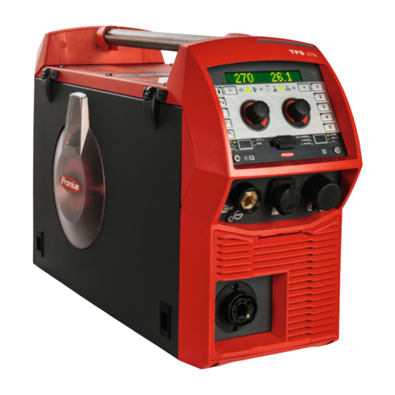
General Device concept The MIG/MAG VW AG/VAS 821 001/ MIG270i power source is a completely digitised, microprocessor-controlled inverter power source with integrated 4- roller wire drive. The modular design and potential for sys- tem add-ons ensure a high degree of flex- ibility. -
Page 22: Warning Notices On The Device
Warning notices Warning notices and safety symbols are affixed to power sources with the CSA test mark on the device for use in North America (USA and Canada). These warning notices and safety symbols must not be removed or painted over. They warn against incorrect operation, as this may result in serious injury and damage. - Page 23 These Operating Instructions All the Operating Instructions for the system components, especially the safety rules Do not dispose of used devices with domestic waste. Dispose of them according to the safety rules. Keep hands, hair, clothing and tools away from moving parts. For example: Cogs Feed rollers Wirespools and welding wires...
-
Page 24: Description Of Warning Notices On The Device
Description of On certain device versions, warning notices are attached to the device. Warning Notices on the Device The arrangement of the symbols may vary. Warning! Watch Out! There are possible hazards as shown by the symbols. Drive rolls can injure fingers. Welding wire and drive parts are at welding voltage during operation Keep hands and metal objects away. - Page 25 Welding sparks can cause explosion or fire. Keep flammables away from welding. Don’t weld near flammables. Welding sparks can cause fires.Have a fire extinguisher nearby and have a watchperson ready to use it. Do not weld on drums or any closed containers. Arc rays can burn eyes and injure skin.
-
Page 26: Welding Packages, Welding Characteristics And Welding Processes
Welding packages, welding characteristics and welding processes General Various welding packages, welding characteristics and welding processes are available with power sources that enable a wide range of materials to be effectively welded. Welding charac- Depending on the welding process and shielding gas mix, various process-optimised teristics welding characteristics are available when selecting the filler metal. - Page 27 galvannealed Characteristics for iron-zinc coated sheet surfaces gap-bridging CMT, PMC Characteristics with very low heat input for optimum gap-bridging ability hot spot Characteristics with hot start sequence, specifically for plug welds and MIG/MAG spot weld joints mix ** also required: Pulse and PMC welding packages Characteristics with process switch between pulsed and dip transfer arc Specially for welding vertical-up seams with cyclic change between a hot and cold sup- porting process phase.
-
Page 28: Summary Of Mig/Mag Pulse Synergic Welding
Characteristics that behave like interval mode for clear weld rippling, especially with alu- minium root CMT, LSC, Standard Characteristics for root passes with powerful arc seam track PMC, Pulse Characteristics with increased seam tracking signal, especially for use with several weld- ing torches on one component. -
Page 29: Summary Of The Pmc Process
Spray arc A short circuit-free transfer of material in the high power range. Summary of the PMC = Pulse Multi Control PMC process PMC is a pulsed arc welding process with high-speed data processing, precise recording of the process status and improved droplet detachment. Faster welding possible with a stable arc and even fusion penetration. -
Page 30: Summary Of The Cmt Process
Summary of the CMT = Cold Metal Transfer CMT process A special CMT drive unit is required for the CMT process. The reversing wire movement in the CMT process results in a droplet detachment with improved dip transfer arc properties. The advantages of the CMT process are as follows Low heat input Less spattering... -
Page 31: System Components
System components General The power sources can be operated with various system components and options. This makes it possible to optimise procedures and to simplify machine handling and opera- tion, as necessitated by the particular field of application in which the power source is to be used. -
Page 33: Operating Controls, Connections And Mechanical Components
Operating controls, connections and mechanical components... -
Page 35: Control Panel
Control Panel General Welding parameters can be easily changed and selected using the adjusting dial. The parameters are shown on the display while welding is in progress. The synergic function ensures that other welding parameters are also adjusted whenever an individual parameter is changed. NOTE! As a result of firmware updates, you may find that your device has certain func- tions that are not described in these operating instructions, or vice versa. - Page 36 Function Process control parameter indicator For the LSC and PMC welding processes Penetration stabilizer indicator Lights up if the penetration stabilizer is active Arc length stabilizer indicator Lights up when the arc length stabilizer is active Left parameter selection The corresponding indicator lights up when a parameter is selected. The following parameters can be selected by pressing the button: Material thickness * In mm or inches...
- Page 37 Arc length stabilizer The "Penetration stabilizer" and "Arc length stabilizer" process control paramet- ers can only be selected when the LSC/PMC welding process is used. The currently adjustable parameter is marked with an arrow. * Synergic parameter When a synergic parameter is changed, the synergic func- tion automatically changes all other synergic parameters to match.
- Page 38 The function varies according to the welding process being used. A description of the various functions can be found in the Welding chapter under the correspond- ing welding process. Special function Any parameter can be assigned to this The function can be selected if a parameter has been saved. * Synergic parameter When a synergic parameter is changed, the synergic function automatically changes all other synergic parameters to match.
- Page 39 PULS SYNERGIC (MIG/MAG pulse synergic welding) SYNERGIC (MIG/MAG standard synergic welding) MANUAL (MIG/MAG standard manual welding) LSC/PMC (LSC = Low Spatter Control, PMC = Pulse Multi Control) Depending on which function package is enabled STICK/TIG (MMA welding/TIG welding) CMT / SP (CMT welding / special programs) (10) USB port For updating the software using a USB Ethernet adapter...
-
Page 40: Displaying Plain Text For Parameters
Displaying plain The left adjusting dial can be used to display the corresponding plain text for each para- text for paramet- meter abbreviation shown on the display. Example: Parameter or entry from the Setup menu has been selected using the right adjusting dial;... -
Page 41: F1/F2 Special Function Parameters, Favourites Button
F1/F2 special function parameters, Favourites but- F1 and F2 special Setting F1 and F2 special function parameters function paramet- I-S [%] ~ 3 sec. ~ 3 sec. Example: the selected parameter I-S is assigned to F1 Select the desired parameter in the Setup menu Further information on the Setup menu can be found from page To assign the selected parameter to F1 or F2, press the parameter selection button for approx. -
Page 42: The Favourites Button
Press the parameter selection button until F1 or F2 lights up: F1 ... left parameter selection F2 ... right parameter selection The stored parameter is shown first, then the currently set value of the parameter. Change the value of the parameter by turning the adjusting dial: F1 ... - Page 43 Select the desired parameter or the desired parent folder in the Setup menu Further information on the Setup menu can be found from page To assign the selected parameter or folder to the Favourites button, press the Favourites button for approx. 3 seconds Next to the parameter or folder and a tick are shown: The selected parameter or folder is now assigned to the Favourites button.
- Page 44 The Favourites button can also be assigned in the Setup menu (page 113).
-
Page 45: Connections, Switches, And Mechanical Components
Connections, Switches, and Mechanical Compon- ents Connections, Function switches and mechanical com- Control panel with display ponents for operating the power source (+) current socket with bayonet latch Blanking cover reserved for the TMC connection socket of the TIG option Welding torch connection for connecting the welding torch (-) current socket with bayonet... - Page 46 Function (12) Wirespool holder with brake for holding standard wirespools weighing up to 19 kg (41.89 lb.) and with a max. diameter of 300 mm (11.81 in) (13) 4 roller drive (12) (13) Side view...
-
Page 47: Installation And Startup
Installation and Startup... -
Page 49: Minimum Equipment For Welding Operations
Minimum equipment for welding operations General Depending on the welding process, a minimum level of equipment is required to work with the power source. The following describes the welding processes and the corresponding minimum equip- ment for welding operations. MIG/MAG gas- Power source cooled welding Grounding (earthing) cable... -
Page 50: Before Installation And Initial Operation
Before installation and initial operation Safety WARNING! Danger due to incorrect operation. This can result in severe personal injury and damage to property. ▶ Do not use the functions described here until you have fully read and understood the Operating Instructions. ▶... -
Page 51: Generator-Powered Operation
CAUTION! An inadequately dimensioned electrical installation can cause serious damage. ▶ The mains lead and its fuse protection must be dimensioned to suit the local power supply. The technical data shown on the rating plate applies. Generator- The power source is generator-compatible. Powered Opera- tion The maximum apparent power S... -
Page 52: Connecting The Mains Cable
Connecting the Mains Cable Safety WARNING! Danger from work that is not carried out properly. This can result in severe personal injury and damage to property. ▶ The work described below may only be performed by trained specialist personnel. ▶ Follow national standards and guidelines. - Page 53 NOTE! Mains cables must be connected to devices in compliance with national standards and guidelines and the work must be carried out by suitably qualified personnel! IMPORTANT! The ground conductor should be approx. 20 - 25 mm (0.8 - 1 in.) longer than the phase conductors.
- Page 54 Tightening torque = 1.2 Nm Tightening torque = 1.2 Nm 5 x TX25, tightening torque = 3 Nm 6 x TX25, tightening torque = 3 Nm...
-
Page 55: Commissioning
Commissioning Safety WARNING! An electric shock can be fatal. If the power source is connected to the grid during installation, there is a danger of seri- ous personal injury and property damage. ▶ Only carry out work on the device when the power source's power switch is in the - O - position. -
Page 56: Establishing A Ground Earth Connection
Establishing a Plug the grounding cable into the (-) ground earth current socket connection Lock the grounding cable in place Use the other end of the grounding cable to establish a connection to the workpiece Connecting the grounding cable Connecting the Before connecting the welding torch, check that all cables, lines and hosepacks are welding torch undamaged and properly insulated. -
Page 57: Inserting/Replacing Feed Rollers
Inserting/repla- In order to achieve optimum wire electrode feed, the feed rollers must be suitable for the cing feed rollers diameter and alloy of the wire being welded. NOTE! Only use feed rollers that are suitable for the wire electrode. An overview of the feed rollers available and their possible areas of use can be found in the spare parts lists. -
Page 58: Inserting The Wirespool
Inserting the CAUTION! wirespool Risk of injury due to springiness of spooled wire electrode. ▶ While inserting the wirespool, hold the end of the wire electrode firmly to avoid injur- ies caused by the wire springing back. CAUTION! Risk of injury from falling wirespool. ▶... -
Page 59: Inserting The Basket-Type Spool
Inserting the bas- CAUTION! ket-type spool Risk of injury due to springiness of spooled wire electrode. ▶ While inserting the basket-type spool, hold the end of the wire electrode firmly to avoid injuries caused by the wire springing back. CAUTION! Risk of injury from falling basket-type spool. -
Page 60: Feeding In The Wire Electrode
Feeding in the CAUTION! wire electrode Risk of injury from springiness of spooled wire electrode. ▶ When inserting the wire electrode into the 4-roller drive, hold the end of the wire electrode firmly to avoid injuries caused by the wire springing back. CAUTION! Risk of damage to the welding torch from sharp end of wire electrode. -
Page 61: Setting The Contact Pressure
Setting the con- NOTE! tact pressure Set the contact pressure in such a way that the wire electrode is not deformed but nevertheless ensures proper wirefeed. Contact pressure standard values for U-slot rollers Steel: 4 - 5 CrNi 4 - 5 Tubular cored electrodes 2 - 3... -
Page 62: Adjusting The Brake
Adjusting the NOTE! brake After releasing the torch trigger the wirespool should stop unreeling. Adjust brake if necessary. STOP STOP Design of the WARNING! Brake Danger from incorrect installation. Serious personal injury and damage to property may result. ▶ Do not dismantle the brake. ▶... -
Page 63: Performing R/L Alignment
Performing R/L IMPORTANT! For optimum welding results, the manufacturer recommends performing alignment an R/L alignment when starting the device for the first time and when any changes are made to the welding system. -
Page 65: Welding Mode
Welding Mode... -
Page 67: Mig/Mag Operating Modes
MIG/MAG Operating Modes General WARNING! Danger from incorrect operation. Possible serious injury and damage to property. ▶ Do not use the functions described here until you have read and completely under- stood these Operating Instructions. ▶ Do not use the functions described here until you have fully read and understood all of the Operating Instructions for the system components, in particular the safety rules! See the Setup menu for information on settings, setting range and units of measurement... -
Page 68: 2-Step Mode
Slope 2: the welding current is steadily lowered until it reaches the final current Gas post-flow A detailed explanation of the parameters can be found in the section headed "Process parameters" 2-step mode "2-step mode" is suitable for Tacking work Short weld seams Automated and robot welding 4-step mode... -
Page 69: Mig/Mag And Cmt Welding
MIG/MAG and CMT welding Safety WARNING! Danger due to incorrect operation. This can result in severe personal injury and damage to property. ▶ Do not use the functions described here until you have fully read and understood the Operating Instructions. ▶... -
Page 70: Retrieving The Currently Set Filler Metal
Retrieving the currently set filler metal Press the "Filler metal info" button The LED on the button lights up and the currently set filler metal is shown on the display: Turn the right adjusting dial The currently set wire diameter is shown on the display: Turn the right adjusting dial The currently set shielding gas is shown on the display: Turn the right adjusting dial... - Page 71 Press the right adjusting dial The first available filler metal is displayed: Select the desired filler metal by turning the right adjusting dial Press the right adjusting dial "diameter?" is shown on the display: * Press the right adjusting dial The first available wire diameter is displayed: Select the desired wire diameter by turning the right adjusting dial Press the right adjusting dial...
-
Page 72: Setting The Welding Parameters
22.8 5O.O Setting the weld- ing parameters Press the button until the desired welding parameter lights up Material thickness Welding current Wire speed Special function Turn the left adjusting dial to change the value of the welding parameter Turn the right adjusting dial to change the value of the welding parameter The amended parameter values are applied immediately. -
Page 73: Mig/Mag Or Cmt Welding
MIG/MAG or CMT CAUTION! welding Risk of injury and damage from electric shock and from the wire electrode emer- ging from the torch. When pressing the torch trigger: ▶ keep the torch away from your face and body ▶ do not point the welding torch at people ▶... -
Page 74: Mig/Mag And Cmt Welding Parameters
MIG/MAG and CMT welding parameters Welding paramet- The following welding parameters can be set and displayed for MIG/MAG pulse synergic ers for MIG/MAG welding, CMT welding and PMC welding: pulse synergic welding, for CMT using the left adjusting dial: welding and PMC welding Material thickness Setting range: 0.1 - 30.0 mm... -
Page 75: Welding Parameters For Mig/Mag Standard Synergic Welding And Lsc Welding
using the right adjusting dial: Arc length correction for correcting the arc length; Setting range: -10 - +10 Factory setting: 0 - ..shorter arc length 0 ... neutral arc length + ... longer arc length Welding voltage in V Setting range: depends on the welding process and welding program selected Before the start of welding, the machine automatically displays a standard value based on the programmed parameters. - Page 76 Setting range: 0.1 - 30.0 mm / 0.004 - 1.18 in. Welding current in A Setting range: depends on the welding process and welding program selected Before the start of welding, the machine automatically displays a standard value based on the programmed parameters. The actual value is displayed during welding. Wire speed for setting a harder, more stable arc Setting range: 0.5 - 25 m/min...
-
Page 77: Welding Parameters For Mig/Mag Standard Manual Welding
- ..shorter arc length 0 ... neutral arc length + ... longer arc length Welding voltage in V Setting range: depends on the welding process and welding program selected Before the start of welding, the machine automatically displays a standard value based on the programmed parameters. -
Page 78: Explanation Of Footnotes
using the right adjusting dial: Welding voltage in V Setting range: depends on the welding process and welding program selected Pulse/dynamic correction for influencing the short-circuiting dynamic at the instant of droplet transfer Setting range: 0 - 10 Factory setting: 0 0 ... -
Page 79: Easyjob Mode
EasyJob mode General The 5 EasyJob buttons enable up to 5 operating points to be saved quickly. The current welding settings are saved. EasyJob mode ~ 3 sec. < 3 sec. > 5 sec. Storing EasyJob operating points To store the current welding settings, press one of the EasyJob buttons for approx. 3 seconds. -
Page 80: Spot Welding
Spot welding Spot welding Spot welding can be carried out in the following welding processes: PULSE SYNERGIC | SYNERGIC | MANUAL | LSC/PMC | SP (CMT) Select the desired welding process by pressing the "Welding process" button Select the MODE by pressing the "Mode" button "Spot"... - Page 81 Wait for the gas post-flow time Lift the torch off the workpiece NOTE! Pre-set start of welding and end of welding parameters are also active for spot welding. ▶ A start of welding / end of welding action for spot welding can be stored in the Setup menu under Process parameters / Start/End.
-
Page 82: Tig Welding
TIG welding Safety WARNING! Danger due to incorrect operation. This can result in severe personal injury and damage to property. ▶ Do not use the functions described here until you have fully read and understood the Operating Instructions. ▶ Do not use the functions described here until you have fully read and understood all of the Operating Instructions of the system components, especially the safety rules. - Page 83 Press the "Welding process" button until the LED for the STICK/TIG welding process lights up and "TIG" is shown on the display. After a short time, the currently set welding current is shown on the display. The welding current indicator lights up. The welding voltage is applied to the welding socket with a three second time lag.
-
Page 84: Igniting The Arc
Igniting the arc The welding arc is ignited by touching the workpiece with the tungsten electrode. Place the gas nozzle on the ignition location so that there is a gap of 2-3 mm (0.08 - 0.12 in.) between the tip of the tungsten electrode and the workpiece Gradually tilt the welding torch up until the tungsten electrode touches the workpiece Raise the torch and tilt it into the normal position - the arc now ignites Carry out welding... -
Page 85: Manual Metal Arc Welding
Manual Metal Arc Welding Safety WARNING! Danger due to incorrect operation. This can result in severe personal injury and damage to property. ▶ Do not use the functions described here until you have fully read and understood the Operating Instructions. ▶... - Page 86 IMPORTANT! For optimum welding results, the manufacturer recommends performing an R/L alignment when starting the device for the first time and when any changes are made to the welding system. STICK Press the "Welding process" button until the LED for the STICK/TIG welding process lights up and "STICK"...
-
Page 87: Welding Parameters For Manual Metal Arc Welding
Welding paramet- The following welding parameters can be set and displayed for manual metal arc weld- ers for manual ing: metal arc welding using the left adjusting dial: Main current in A Setting range: depends on the power source available Before the start of welding, the machine automatically displays a standard value based on the programmed parameters. -
Page 89: Setup Settings
Setup Settings... -
Page 91: Setup Menu - Overview
Setup menu - overview Entering/exiting the Setup menu To enter the Setup menu, press the "Welding process" and "Mode" buttons at the same time "Process parameters" is shown on the display. To exit the Setup menu, press the "Welding process" and "Mode" buttons at the same time... -
Page 92: Setup Menu - Overview
Setup menu - overview Settings Process param. Language xx Display System back Start/End Gas-setup Process c. Spot welding Components Unit CLS [s] STICK Standard UIBS Web-PWreset SynchroPulse Information DRSL. Process Mix F1/F2 Param iJob xx R/L-check / align- Favourite ment <... -
Page 93: Process Parameters
Process parameters Process paramet- The following process parameters can be set and displayed for the start and end of weld- ers for start of ing: welding/end of welding Starting current For setting the starting current for MIG/MAG welding (e.g. aluminium welding start-up) Setting range: 0 - 200% (of welding current) Factory setting: 135% Start arc length correction... -
Page 94: Process Parameters For Gas-Setup
Setting range: -10 - +10% (of welding voltage) Factory setting: 0 - ..shorter arc length 0 ... neutral arc length + ... longer arc length Final current time For setting the length of time for which the final current is to be active Setting range: off / 0.1 - 10.0 s Factory setting: off to activate/deactivate the SFI function (Spatter Free Ignition of the arc) -
Page 95: Process Parameters For Process Control
Gas pre-flow For setting the gas flow time before the arc is ignited Setting range: 0 - 9.9 s Factory setting: 0.1 s Gas post-flow For setting the gas flow time after the arc has gone out Setting range: 0 - 9.9 s Factory setting: 0.5 s Gas set value For specifying the gas set value in l/min... - Page 96 Application examples Penetration stabilizer = 0 m/min (not activated) I [A] [m/min] t [s] < s > x Penetration stabilizer = 0 m/min (not activated) Changing the contact tube distance (h) alters the resistance in the welding circuit due to the longer stick out (s The constant voltage control for constant arc length causes a reduction in the mean cur- rent value and hence a smaller penetration (x...
-
Page 97: Arc Length Stabilizer
I [A] [m/min] 0,5 m/min t [s] < s > x Penetration stabilizer = 0.5 m/min (activated) To minimise the change in welding current if the stick out is changed (s ==> s ), the wire speed is increased or reduced by 0.5 m/min. In the example shown, the stabilising effect is obtained without a change in current up to the set value of 0.5 m/min (Position 2). - Page 98 I [A] [m/min] U [V] t [s] > L > L Arc length stabilizer = 0 / 0.5 / 2.0 Activating the arc length stabilizer reduces the arc length until short circuits start to occur. The frequency of the short circuits is controlled and kept stable. Increasing the arc length stabilizer causes a further shortening of the arc length (L1 ==>...
-
Page 99: Combination Of Penetration Stabilizer And Arc Length Stabilizer
Combination of Example: Stick out change penetration sta- bilizer and arc Arc length stabilizer without penetration stabilizer length stabilizer The advantages of a short arc are main- tained even if the stick out is changed, since the short-circuit properties stay the same. -
Page 100: Process Parameters For Spot Welding
Process paramet- ers for spot weld- Spot welding time 0.1 - 10.0 s Factory setting: 1.0 s Process paramet- The following process parameters can be set and displayed for the system components ers for monitor- of a welding system: ing and compon- ents Cooling unit mode To determine whether a cooling unit is to be switched on or off, or operated automatically... -
Page 101: Process Parameters For Electrode Setup
(only in conjunction with the OPT/i gas controller option) Setting range: auto, 0.90 - 20.0 Factory setting: auto (the correction factor is automatically set for standard gases from the Fronius welding database) Process paramet- The following process parameters can be set and displayed for manual metal arc weld-... - Page 102 con - 20 A / V Load line for rod electrode U (V) Load line for rod electrode where arc length is increased Load line for rod electrode where arc length is reduced Characteristic where "I-constant" parameter is selected (constant welding current) Characteristic where "0.1 - 20"...
- Page 103 Example of pre-set arc-force dynamic where characteristic (5) or (6) is selected Possible change in the current where characteristic (5) or (6) is selected, as a function of the welding voltage (arc length) Operating point where arc length is long Operating point where welding current I is set Operating point where arc length is short...
-
Page 104: Process Parameters For Tig Setup
Process paramet- The following process parameters can be set and displayed for TIG welding: ers for TIG setup Break voltage For setting a voltage, at which the welding process can be ended by slightly lifting the TIG welding torch. Setting range: 10.0 - 30.0 V Factory setting: 14.0 V Comfort Stop Sensitivity To activate/deactivate the TIG Comfort Stop function... -
Page 105: Process Parameters For Synchropulse
Process paramet- The following process parameters can be set for SynchroPulse welding: ers for Syn- Syn-Puls chroPulse SynchroPulse To activate/deactivate SynchroPulse Setting range: off / on Factory setting: off vd (1) Wire speed For setting the average wire speed and therefore the welding power for SynchroPulse Setting range: 1.0 - 25.0 m/min (40 - 985 ipm) Factory setting: 5 m/min dFd (2) - Page 106 - ..short arc 0 ... uncorrected arc length + ... longer arc [m/min] 1 / F 25 % 75 % t [s]...
-
Page 107: Process Parameters For Process Mix
Process paramet- The following process parameters for mixed processes can be set under "Process mix": ers for Process PMC mix I [A] [m/min] t [ms] Mixed process between PMC and LSC welding process. A cold LSC process phase follows a hot PMC process phase as part of a cycle. - Page 108 The wire speed value can also be specified or changed in the Process mix parameters. Arc length correction Is taken from the welding parameters Setting range: -10.0 - +10.0 The arc length correction value can also be specified or changed in the Process mix parameters.
-
Page 109: R/L Alignment
Lpc (1) Lower power correction To set the energy input in the cold process phase in a mixed process Setting range: -10.0 - +10.0 Factory setting: 0 If the lower power correction is increased, this results in a higher wire speed and there- fore higher energy yield in the cold LSC process phase. - Page 110 To exit the Setup menu, press the "Welding process" and "Mode" buttons at the same time...
-
Page 111: Settings
Settings General NOTE! Because of firmware updates, certain functions may be available for your device but not described in these operating instructions or vice versa. In addition, individual figures may also differ slightly from the operating elements of your device. However, the function of these operating elements is identical. WARNING! Operating the device incorrectly can cause serious injury and damage. -
Page 112: Setting The Standards
Setting the stand- Select Setup menu / Settings / View / Standard ards Press the right adjusting dial The first of the available standards is displayed. Select the desired standard by turning the right adjusting dial: Name of filler metal according to European standards (e.g. -
Page 113: Setting The Favourites Button Via The Setup Menu
Turn the right adjusting dial to determine under which special function the parameter should be stored: - ... the parameter is not assigned to a special function/a stored parameter is deleted F1 ... parameter is stored under special function F1 F2 ... -
Page 114: Setting The Interior Lighting
Current arc energy in kJ The arc energy is the sum total of the arc power and calculates the heat input of the weld seam most recently produced. If the weld seam length is known the electrical energy input can be calculated: E = IE / L Electrical energy input in kJ/cm Arc energy in kJ... -
Page 115: Restoring The Factory Settings
Restoring the Select Setup menu / Settings / System / FAC factory settings Press the right adjusting dial Turn the right adjusting dial to select "Yes", thereby restoring the power source to the factory settings Press the right adjusting dial The process parameters and machine default values are immediately reset to the factory settings without any further warning. -
Page 116: Setting The Mode For Spot Welding
The following can now be set and carried out on the JobMaster welding torch: Mode SynchroPulse Gas test Setting the mode Select Setup menu / Settings / System / SPm for spot welding Press the adjusting dial Turn the adjusting dial and select the desired mode for spot welding 2-step = spot welding in 2-step mode: The spot welding process runs for as long as the torch trigger is kept pressed and ends no later than at the expiry of the spot welding time. -
Page 117: Setting The Language
Setting the language Setting the lan- Access the Setup menu guage Select the language Press the right adjusting dial The language abbreviation of the currently set language is highlighted on the display. Select the desired language by turning the right adjusting dial The following languages can be selected: Czech Dutch... -
Page 118: Keylock
Keylock Keylock To activate the keylock Press the "Welding process" and left parameter selection buttons at the same time Alternatively, the "Mode" and right parameter selection buttons can be pressed. The key symbol and a tick are shown on the display: The following functions are disabled: The following functions are available: the adjusting dial functions... -
Page 119: Troubleshooting And Maintenance
Troubleshooting and Maintenance... -
Page 121: The Error Menu
The Error menu The Error menu Notifications, warnings and errors are shown on the display with the corresponding num- ber. If an error occurs, the Error menu is always in the foreground. Pressing the right adjusting dial opens the Error menu on "confirm". Pressing the right adjusting dial a second time confirms the error;... -
Page 122: Troubleshooting
Troubleshooting General The power sources are equipped with an intelligent safety system, meaning it has been possible to dispense with nearly all fuses. After a possible malfunction has been remedied, the power source can be used again as normal. Possible malfunctions, warning notices or status codes are shown on the display as plain text dialogues. - Page 123 No welding current Mains switch is on, overtemperature is displayed Cause: Overload; the duty cycle has been exceeded Remedy: Check duty cycle Cause: Thermostatic automatic circuit breaker has been tripped Remedy: Wait until the power source automatically comes back on after the end of the cooling phase Cause: Limited supply of cooling air...
- Page 124 Poor-quality weld properties Cause: Incorrect welding parameters Remedy: Check settings Cause: Poor ground earth connection Remedy: Establish good contact with workpiece Cause: Too little or no shielding gas Remedy: Check gas pressure regulator, gas hose, gas solenoid valve, welding torch gas connection, etc.
- Page 125 Welding torch gets very hot Cause: Welding torch is inadequately sized Remedy: Observe duty cycle and load limits Cause: For water-cooled systems only: Coolant circulation too low Remedy: Check coolant level, coolant flow volume, coolant contamination etc. More details can be found in the cooling unit’s Operating Instructions...
-
Page 126: Service, Maintenance And Disposal
Service, maintenance and disposal General Under normal operating conditions, the power source requires only a minimum of care and maintenance. However, it is vital to observe some important points to ensure the welding system remains in a usable condition for many years. Safety WARNING! An electric shock can be fatal. -
Page 127: Technical Data
Technical data... -
Page 129: Average Consumption Values During Welding
Average consumption values during welding Average wire Average wire electrode consumption at a wire speed of 5 m/min electrode con- 1.0 mm wire 1.2 mm wire 1.6 mm wire sumption during electrode dia- electrode dia- electrode dia- MIG/MAG welding meter meter meter Steel wire electrode... -
Page 130: Technical Data
Technical data Explanation of The duty cycle (D.C.) is the period of a ten minute cycle in which the device may be the Term Duty operated at the stated power without overheating. Cycle NOTE! The D. C. values cited on the rating plate relate to an ambient temperature of 40 °C. If the ambi- ent temperature is higher, the D.C. -
Page 131: Vw Ag/Vas 821 001/Mig270I
VW AG/VAS 821 Mains voltage (U 400 V 001/MIG270i Max. effective primary current (I 9.7 A 1eff Max. primary current (I 15.3 A 1max Mains fuse protection 16 A slow-blow Mains voltage tolerance -15 / +15 % Grid frequency 50/60 Hz Cos phi (1) 0.99 Max. - Page 132 The wirefeeder for the VW AG/VAS 821 001/MIG270i is integrated in the power source. Interface to a 230/400 V and 50 Hz public grid...
- Page 133 VW AG/VAS 821 Mains voltage (U 200 V 230 V 001/MIG270i MV Max. effective primary current (I 16.9 A 15.1 A 1eff Max. primary current (I 26.5 A 23.7 A 1max Mains fuse protection 35 A slow-blow Mains voltage (U 380 V 400 V 460 V...
-
Page 134: Overview With Critical Raw Materials, Year Of Production Of The Device
35,9 W Power source efficiency at 270 A / 90 % 30,8 V The wirefeeder for the VW AG/VAS 821 001/MIG270i MV is integrated in the power source. Interface to a 230/400 V and 50 Hz public grid Overview with... -
Page 135: Appendix
Appendix... -
Page 136: Vw Ag/Vas 821 001/Mig270I Mv
Spare parts list: VW AG/VAS 821 001/MIG270i VW AG/VAS 821 001/MIG270i 4,075,170,450 VW AG/VAS 821 001/MIG270i/MV 4,075,170,459 44,0550,0060 42,0300,2945 38,0008,0035 42,0300,2921 42,0401,0399 42,0300,2601 42,0399,0085 42,0400,0352 42,0405,0905 42,0201,4658 44,0001,1458 42,0401,0399 42,0300,3105 42,0399,0085 42,1400,0099 42,0405,0905 42,1400,0100 42,1400,0099 44,0001,1462 44,0001,1419 42,1400,0102 44,0001,1527,Z 40,0001,0522... - Page 137 41,0015,0018 43,0004,5492 43,0001,3443 43,0004,4354 43,0001,1416 USB-MCU 43,0001,3440 42,0300,7236 43,0001,3457,Z 42,0300,7304 42,0201,3593 (MV) 42,0405,0845 42,0405,0823 4,071,194,Z 33,0010,0432 (ASU2700) 33,0010,0433 (MV) 43,0004,2071 42,0405,0844 43,0001,1138 42,0409,0502 43,0001,1435 43,0003,1241 4,071,273,Z 4,071,162,Z (NVP-COMP) (BPS2700C) 42,0405,1244 43,0001,1451 41,0007,0166 42,0401,1148 43,0003,0031 4,071,179,Z (ELC3200C) 4,071,288,Z (ELCCAN3200) 43,0001,3435 43,0001,3447 42,0300,7303 43,0001,1186 42,0405,0828...
- Page 138 motor plate alu 4R s - compact 44,0001,1405 - U 0,8 44,0001,1406 - U 0,9-1,0 44,0001,1407 - U 1,2 44,0001,1408 - U 1,4-1,6 44,0001,1431 - R 1,2 - R 1,4 44,0001,1432 44,0001,1433 - R 1,6 42,0405,1095 t o r 42,0407,0667 48,0001,0052 t o r 44,0350,3201...
- Page 140 FAN Austria GmbH Herderstraße 44 A-4600 Wels www.fan-austria.com office@fan-austria.com deutschland@fan-austria.com Tel. ++43/7242/44432 Fax. ++43/7242/69438...
Need help?
Do you have a question about the VW AG/VAS 821 001/MIG270i and is the answer not in the manual?
Questions and answers