Bradford White FT Series Installation And Operation Instruction Manual
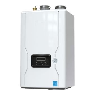
Wall-mounted, modulating gas, condensing, combination boiler
Hide thumbs
Also See for FT Series:
- Installation and operation instruction manual (92 pages) ,
- Installation and instruction manual (36 pages) ,
- Manual (4 pages)
Table of Contents
Advertisement
Quick Links
Installation and Operation Instructions
FOR YOUR SAFETY: This product must be installed and serviced by a professional service technician,
qualified in hot water boiler and heater installation and maintenance. Improper installation and/or operation
could create carbon monoxide gas in flue gases which could cause serious injury, property damage, or
death. Improper installation and/or operation will void the warranty.
If the information in this manual is not
followed exactly, a fire or explosion may
result causing property damage, personal
injury or loss of life.
Do not store or use gasoline or other
flammable vapors and liquids in the vicinity of
this or any other appliance.
WHAT TO DO IF YOU SMELL GAS
• Do not try to light any appliance.
• Do not touch any electrical switch; do not
use any phone in your building.
• Immediately call your gas supplier from a
nearby phone. Follow the gas supplier's
instructions.
• If you cannot reach your gas supplier, call
the fire department.
Installation and service must be performed
by a qualified installer, service agency, or gas
supplier.
Installation and Operation
Instructions for
THE
Wall-Mounted, Modulating
Gas, Condensing, Combination Boiler
Model FTCW
140,000 BTU/h
199,000 BTU/h
WARNING
FT
SERIES
•
Natural Gas (NG) - Factory Configuration
•
Propane Gas (LP) - Field-Convertible
Assurez-vous de bien suivres les instructions
données dans cette notice pour réduire au
minimum le risque d'incendie ou d'explosion
ou pour éviter tout dommage matériel, toute
blessure ou la mort.
Ne pas entreposer ni utiliser d'essence ou ni
d'autres vapeurs ou liquides inflammables dans
le à proximité de cet appareil ou de tout autre
appareil.
QUE FAIRE SI VOUS SENTEZ UNE ODEUR DE
• Ne pas tenter d'allumer d'appareils.
• Ne touchez à aucun interrupteur. Ne pas vous servir
des téléphones dans le bâtiment où vous vous
trovez.
• Appelez immédiatement votre fournisseur de
gaz depuis un voisin. Suivez les instructions
du fournisseur.
• Si vous ne pouvez rejoindre le fournisseur de
gaz, appelez le sservice des incendies.
L'installation et l'entretien doivent être assurés par
un installateur ou un service d'entretien qualifié
ou par le fournisseur de gaz.
Document 1487
AVERTISSEMENT
GAZ:
Advertisement
Table of Contents

Related Manuals for Bradford White FT Series


Summary of Contents for Bradford White FT Series
- Page 1 Installation and Operation Instructions Document 1487 Installation and Operation Instructions for SERIES Wall-Mounted, Modulating Gas, Condensing, Combination Boiler Model FTCW 140,000 BTU/h 199,000 BTU/h • Natural Gas (NG) - Factory Configuration • Propane Gas (LP) - Field-Convertible FOR YOUR SAFETY: This product must be installed and serviced by a professional service technician, qualified in hot water boiler and heater installation and maintenance.
-
Page 2: Table Of Contents
Page 2 TABLE OF CONTENTS SECTION 1 Introduction About this Installation Manual ......3 4.16 Pressure Relief Valve ........42 4.17 Disposal of Condensate ......43 Included in the Box ..........4 4.18 DHW Flow Restrictors ........44 SECTION 2 Product Characteristics 4.19 Electrical Wiring Connections ....45 Model Nomenclature (model number) ....5 4.20 DIP Switches .............46... -
Page 3: Section 1 Introduction
TOP VIEW The FT Series Wall Mounted, Combination Boiler Page 3 SECTION 1 Introduction For details on Combustion Air and Venting, See page 18 About this through to page 26 Installation Manual All installations must be made in This manual provides the... -
Page 4: Included In The Box
Page 4 Included in the Box Item Description Wall Mounted, Combination Boiler FTCW140 / 199 Installation Instructions and User’s Manual Condensate Hose FT1894 Wall Mount Bracket 2 types of Wall Anchors Pressure Relief Valve (CH LINE 3/4˝ 30psi) Model: CASH ACME F-82... -
Page 5: Section 2 Product Characteristics
The FT Series Wall Mounted, Combination Boiler Page 5 1.2 Included in the Box (continued) Items Descriptions 3” Mesh Screens O-Ring and Gasket Kit Outdoor Sensor with screws and anchors FTCW140 FTCW199 4.5 GPM Flow Restrictor (dark blue) Propane Conversion Orifice This additional 4.5 GPM (dark blue) is provided with the FTCW140 for use in higher inlet water... -
Page 6: Specifications
Page 6 Specifications, 140 Model Name FTCW140 140,000 Btu/h Gas Input Rate 14,000 Btu/h 35°F Rise 7.1 GPM Hot Water Capacity 45°F Rise 5.5 GPM 77°F Rise 3.2 GPM Installation Indoor / Wall hung type Sealed Combustion Direct / Single Vent / Concentric Flue System Vent Vent Run / Vent Material... - Page 7 The FT Series Wall Mounted, Combination Boiler Page 7 Specifications, 199 Model Name FTCW199 199,000 Btu/h Gas Input Rate 19,900 Btu/h 35°F Rise 9.88 GPM Hot Water Capacity 45°F Rise 7.7 GPM 77°F Rise 4.8 GPM Installation Indoor / Wall hung type...
-
Page 8: Dimensions
Page 8 Dimensions FTCW140 7/8” 3/8” 3/4” 5/8” 7/8” 3/4” 3/4” 3/8” 3/8” BOTTOM VIEW TOP VIEW FRONT VIEW Description Diameter Air Intake collar 3" Vent Pipe Collar 3" ‘CH’ Supply 1" NPT ‘CH’ Return 1” NPT ‘DHW’ Outlet 3/4” NPT 8page (140) ‘DHW’... - Page 9 The FT Series Wall Mounted, Combination Boiler Page 9 2.3 Dimensions FTCW199 5/8” 3/4” 3/4” 15.0" 5/8” 1/4” 7/8” 1/4” 1/2” BOTTOM VIEW TOP VIEW FRONT VIEW Description Diameter Air Intake collar 3" Vent Pipe Collar 3" ‘CH’ Supply 1" NPT 9page (199) ‘CH’...
-
Page 10: Names Of Components
Page 10 Names of Components FTCW140 Name of Component Name of Component Condensate Trap Air Vent (air eliminator) Blocked Condensate Switch Pressure Relief Valve Mixing Valve Air Intake Collar Terminal Block Air Gas Mixing Pipe Control Panel and Display Gas Valve Heat Exchanger DHW Water Tank Ignition Transformer... - Page 11 The FT Series Wall Mounted, Combination Boiler Page 11 Names of Components FTCW199 Name of Component Name of Component Condensate Trap Air Vent (air eliminator) Blocked Condensate Switch Pressure Relief Valve Mixing Valve Air Intake Collar Terminal Block Gas Valve...
-
Page 12: Product Flow Paths And Characteristics
Page 12 Product Flow Paths and Characteristics 2.5.1 Central Heating flow. Combination Boiler Heating Mode. Water in the heating pipe is used for space heating. FTCW140 FTCW FTCW140 2.5.2 Domestic Hot Water flow. Combination Boiler Domestic Hot Water Mode. Note: The model 140 is shown in Cold water passes through the exchanger and is this illustration. -
Page 13: Section 3 Safety Regulations
The FT Series Wall Mounted, Combination Boiler Page 13 SECTION 3 Safety Regulations Safety Symbols WARNING WARNING To avoid product damage, personal injury, or even FOR YOUR SAFETY READ BEFORE possible death, carefully read, understand, and OPERATING follow all the instructions in the Installation and... -
Page 14: Safety Precautions And Proper Use
Page 14 Safety Precautions and Proper Use damaging condition that might affect the operation of the unit. Boiler must be checked by a qualified technician before resuming operation. DO NOT use this Boiler if any part has been under water. Immediately call a qualified technician for inspecting the Boiler and replacing any part of the DANGER control system and gas control which have been... - Page 15 The FT Series Wall Mounted, Combination Boiler Page 15 2. Caution for Ventilation Before Operation Make sure that there is sufficient inflow and outflow of air ventilation while using the unit. 1. Check the Gas Type (NG/LP) When using or If the ventilation is improper, combustion quality may moving the unit for the first time.
-
Page 16: Section 4 Installation
Page 16 SECTION 4 Installation Location and Clearances WARNING Installations must comply with The FT must be mounted to a suitable wall by a • All the local, state, provincial, and national codes, qualified heating contractor under the guidelines of a laws, regulations and ordinances. -
Page 17: Wall Mount Bracket
The FT Series Wall Mounted, Combination Boiler Page 17 Wall Mount Bracket 3" to Top of Unit • The installation height and location for your Anchors FT depends on your installation scenario. With all clearances considered, and given adequate positioning for air supply... -
Page 18: Combustion Air
Page 18 Combustion Air FT boilers must have provisions for combustion and ventilation air in accordance with the applicable requirements for Combustion Air Supply and Ventilation vertical or horizontal duct to the outdoors or spaces in the National Fuel Gas Code, ANSI Z223 1; or in that directly communicate with the outdoors and shall Canada, the Natural Gas and Propane Installation Code, have a minimum free area of 1 square inch per 3000... - Page 19 The FT Series Wall Mounted, Combination Boiler Page 19 NOTICE AVIS The instructions for the installation of the venting Les instructions d'installation du système system shall specify that the horizontal portions of d'évacuation doivent préciser que les sections the venting system shall be supported to prevent horizontales doivent être supportées pour prévenir...
-
Page 20: Venting (Exhaust)
Page 20 Venting (Exhaust) WARNING All venting must be installed according to this manual NOTICE and any other applicable local codes, including but not limited to, ANSI Z224.1/NFPA 54, CAN/CSA DO NOT COMMON VENT FT UNITS. FT B149.1 and ULC-S636. Failure to follow this manual units are never permitted to share a vent with and applicable codes may lead to property damage, Category I appliances. -
Page 21: General Location Guideline
The FT Series Wall Mounted, Combination Boiler Page 21 be from a certified manufacturer. WARNING 4 . Vent system components must not be Failure to vent this Boiler in accordance with these mixed with alternate manufacturers instructions could cause a fire, resulting in severe certified components and/or unlisted property damage, personal injury or death. -
Page 22: Locations For Vent Pipe Terminator
Page 22 Locations for Vent Pipe Terminator Canadian Installations 1 U.S. Installations 2 A = Clearance above grade, veranda, porch, deck, or balcony B = Clearance to window or door that may be ● 6 in (15 cm) for appliances ≤ 10,000 Btuh (3 kW) ●... -
Page 23: Venting Requirements In The Commonwealth Of Massachusetts
The FT Series Wall Mounted, Combination Boiler Page 23 4.6.1 Venting Requirements in the Commonwealth of Massachusetts Approved Carbon Monoxide Detectors. Each In Massachusetts the following items are required if carbon monoxide detector shall comply with NFPA the side-wall exhaust vent termination is less than 720 and be ANSI/UL 2034 listed and IAS certified. -
Page 24: Common Vent Test
Page 24 Common Vent Test NOTE: This section does not describe a method for common venting FT units. It describes what must be done when an existing unit is removed from a common vent system. AVIS Au moment du retrait d'une chaudière existante, les mesures suivantes doivent être prises pour chaque appareil toujours raccordé... -
Page 25: Air Supply And Vent Connections
**When using 2" Combustion Air & Vent pipe, Propane Models are limited to 25 equivalent feet (7.5 M) of vent and 25 equivalent feet (7.5 M) of combus The FT Series Wall Mounted, Combination Boiler Page 25 Air Supply and Vent Connections 4.8.1... -
Page 26: Indoor Combustion Air
Page 26 4.8.2 Indoor Combustion Air Read and Follow Sections 4.3 Guidelines First. 1. Insert the termination end cap into the intake air duct. 2. Provide two openings to allow for circulation of combustion air as specified by ANSI Z224.1/NFPA 54. In Canada refer to CAN/CSA B-149.1 NOTE: The FT needs fresh air for safe operation and must be installed so there are provisions for... - Page 27 The FT Series Wall Mounted, Combination Boiler Page 27 4.9 Vent / Air Pipe Termination (continued) Horizontal Vent Termination • Direct Vent - Sidewall Termination Exterior Wall Vent Screens are required 1” MIN Exhaust Elbow 12” MIN 12” MIN Exhaust...
- Page 28 Page 28 • Direct Vent - Optional Side wall Terminations Exterior Wall Concentric Vent Termination • Direct Vent - Optional Horizontal Exterior Wall Side Wall Kit and Vertical Concentric Vent (2” or 3”) NOTE: Concentric Vent Terminations cannot be Side Wall Kit less than 12”...
-
Page 29: Gas Supply And Piping
The FT Series Wall Mounted, Combination Boiler Page 29 4.10 Gas Supply and Piping WARNING: Gas piping should be supported by suitable hangers or Open flame can cause gas to ignite and result in floor stands, not the appliance. property damage, severe injury, or loss of life. - Page 30 Page 30 4.10 Gas Supply and Piping (cont) The gas shut-off valve in the gas supply line should The gas connection fitting is, be installed close to the unit. 3/4” male NPT on FTCW140 models To facilitate any future maintenance, it is also 3/4”...
- Page 31 The FT Series Wall Mounted, Combination Boiler Page 31 Suggested Natural Gas (NG) Layout NOTE: Total gas supply capacity must not be less than the total demand capacity of the connected appliances. Gas Regulator (Supply Press 12˝ ) Suggested Propane Gas (LP) Layout...
-
Page 32: Gas Supply Pressure
Page 32 4.11 Gas Supply Pressure Refer to the illustration. Offset Adjustment. Do Not Adjust without using a combustion analyzer to verify adjustment. Adjust ONLY when in MIN Fire and when using a combustion analyser. See Section 4.12 for step by step details. Gas Outlet / Manifold Pressure Port Inlet Gas Pressure Port FTCW140... -
Page 33: Adjusting Combustion
NOT attempt to adjust CO 2 at MAX Fire. ONLY adjust CO 2 in MIN Fire operation. WARNING The FT Series, Wall Combi, Gas Conversion Kit Document 4288D Installer is required to verify combustion settings as part Standard Factory Setting is for of the installation process. -
Page 34: High Altitude Installations
Page 34 Adjusting Combustion (continued) NG' type combustibility LP' type combustibility Manifold pressure Manifold pressure 2''/3'' VENT 2''/3'' VENT MAX FIRE ‐0.130''WC ‐0.100''WC MAX FI FTCW140 FTCW199 MIN FIRE 0.004''WC 0.002''WC MIN FI bility NG' type combustibility LP' combustibility Manifold pressure 2" VENT 3" VENT 2" VENT 3" VENT MAX FIRE ‐0.129" WC ‐0.314 WC ‐0.169" WC ‐0.173" WC FTCW199 MIN FIRE ‐0.015" WC ‐0.015" WC ‐0.015" WC ‐0.015" WC Table 11. -
Page 35: Natural Gas To Propane Conversion
The FT Series Wall Mounted, Combination Boiler Page 35 The FT Series, Wall Combi, Gas Conversion Kit Document 4388 4.14 Natural Gas to Propane Conversion 37page Kit # RXXXXX The FT Series, wall combi, condensing boiler is confi gured for Natural Gas (NG) from the factory. - Page 36 Page 36 4.14 Natural Gas to Propane Conversion (cont) The FT Series, Wall Combi, Gas Conversion Kit Document 4388 Figure A Figure B Gas Valve Combustion Test Port Figure C ORIFICE FTCW140 PACKING FTCW199 Gas Valve Figure B Gas Valve...
- Page 37 The FT Series Wall Mounted, Combination Boiler Page 37 The FT Series, Wall Combi, Gas Conversion Kit Document 4388 4.14 Natural Gas to Propane Conversion (continued) MIN Fire Normal Operation MAX Fire Normal Operation NG Natural LP Propane 3” Vent Size 2”...
- Page 38 Page 38 The FT Series, Wall Combi, Gas Conversion Kit Document 4388 4.14 Natural Gas to Propane Conversion (continued) NOTE: Installer is required to verify combustion settings as part of the installation process. CO should not exceed 200 ppm. Natural Gas (NG)
-
Page 39: Plumbing Guidelines
The FT Series Wall Mounted, Combination Boiler Page 39 4.15 Plumbing Guidelines 4.15.1 External Plumbing and Water Connection Guidelines - Ensure pipe material meets local codes and industry CAUTION standards. - The pipe end must be clean and free of debris. -
Page 40: Zoning With Zone Valves
Page 40 Plumbing Guidelines (continued) 4.15.4 Zoning with zone valves - In a valve based system, there is one circulator pump at the boiler and each heating zone has a zone valve which opens when the zone demands. - Each thermostat is wired directly to the corresponding SECONDARY LOOP zone valve. -
Page 41: Zoning With Circulation Pumps
The FT Series Wall Mounted, Combination Boiler Page 41 4.15.5 Zoning with circulation pumps - In a pump based system, each heating zone of has its own circulator pump which runs when the zone demands. - Each zone thermostat goes to a controller which controls the pumps. -
Page 42: Pressure Relief Valve
Page 42 4.16 Pressure Relief Valve External pressure relief valves must be installed. Observe the following. Failure to comply with the guidelines on installing the pressure relief valve and discharge piping can result in personal injury, death or substantial property damage. WARNING Do not operate this appliance before the pressure relief valve supplied is installed with sufficient... -
Page 43: Disposal Of Condensate
The FT Series Wall Mounted, Combination Boiler Page 43 4.17 Disposal of Condensate High efficiency gas condensing Boilers create condensation when operating. Condensation has acidic (pH) of approximately 4-5. Condensate must be drained in accordance with all local regulations. Follow your local code with regards to the disposal of condensation. -
Page 44: Dhw Flow Restrictors
Page 44 4.18 DHW Flow Restrictor Flow Restrictors are factory installed. Rated at 3.2 WARNING GPM for the model 140 and 7.0 GPM for the model 199, both of these factory installed restrictors are white If the appliance has been filled and operational, in color. -
Page 45: Electrical Wiring Connections
The FT Series Wall Mounted, Combination Boiler Page 45 4.19 Electrical Wiring Connections FTCW140 and FTCW199 Terminal Blocks Manual Switch 0-10V O / S L W C MAIN POWER CH/BOILER PUMP INPUT Low Water Outdoor 0 - 10V Thermostat Cut Off... -
Page 46: Dip Switches
External Service Thermostat Circulator (14 Gauge Wire) Pump Endswitch (14 Gauge Wire) (18 Gauge Wire) The FT Series, Wall Combi, Gas Conversion Kit Document 4388 4.20 DIP Switches MIN Fire Normal Operation MAX Fire Normal Operation NG Natural LP Propane 3”... -
Page 47: Control Board, Electrical Diagram
The FT Series Wall Mounted, Combination Boiler Page 47 4.21 Control Board, Electrical Diagram Control Board... -
Page 48: Ladder Diagram
Page 48 4.22 Ladder Diagram level Air Pressure Sensor... -
Page 49: Electrical Connections (Table)
The FT Series Wall Mounted, Combination Boiler Page 49 4.23 Electrical Connections, (table) Connector Description HT SELV #, Location, Type Label GROUND HT (120V~) Power Supply Line HT (120V~) Not Used HT (120V~) Igniter HT (120V~) L(HT) Pump : CH... - Page 50 Page 50 Electrical Connections , (table) (continued) Connector Description HT SELV #, Location, Type Label Flame Detect Sensor SELV (5V) OP.S Operating water temperature sensor SELV (5V) DH.S DHW temperature sensor SELV (5V) Return temperature sensor SELV (5V) LWD1140-14 BG.S Venting (Exhaust) temperature sensor SELV (5V) ST.S...
-
Page 51: Section 5 Control Display And Operation
The FT Series Wall Mounted, Combination Boiler Page 51 53page SECTION 5 Control Display and Operation Control Dial and Buttons Status Light (constant green when operating normally) The Control Display The Control Display has a Control Dial (E), 4 buttons (A, B, C, D), and a Liquid Crystal Display (with 72 back-lit segments). -
Page 52: Lcd Overview
Page 52 LCD Overview Anti-Freeze Storage Lock Communicating Central Mode Heating Heat Status and Installer Summer Modes Mode (warm weather Flame shutdown) Signal Outside Temp Mode or 0-10V Numeric Display Pump Domestic Hot Water Mode CH mode Central Heat mode icon can be adjusted Anti-freeze mode Anti-freeze mode icon Storage Heating mode... -
Page 53: Operating Mode
The FT Series Wall Mounted, Combination Boiler Page 53 Operating Mode Operating Mode After the Power is turned on, and/or the Control Display is turned on , the Control Display 55page will go through a ‘Start Up’ checklist and briefly show a sequence of diagnostic codes before entering into the ‘Operating Mode. -
Page 54: Status Display Mode
Page 54 56page Status Display Mode Digital Display Status Display Parameter Description O:ot Outdoor temperature Current Outdoor temperature A: Li or A: GA Flow unit Current flow value(Li: L/m, GA: GPM) b: It CH Return Water Temperature Current Return Water Sensor Temperature C: Fr Fan rpm Current fan rpm value... -
Page 55: Dhw Set Point Change Mode
The FT Series Wall Mounted, Combination Boiler Page 55 57page DHW Set Point Change Mode DHW Set Point Change Modes The display shows the following information when changing water heating temperature set points. Changing between Celsius and Fahrenheit When the button D... -
Page 56: Set Point Change Mode
Page 56 58page CH Set Point Change Mode Changing between Celsius and Fahrenheit When the button D is pressed (for more than 5 seconds), temperature unit will toggle between °C and °F. Indicate Example Current Operating Temperature 110°F 58page Temperature sign Celsius or Fahrenheit letter °C or °F Display and Controller are communicating If flame detected... -
Page 57: Installer Parameters
59page The FT Series Wall Mounted, Combination Boiler Page 57 Installer Parameters WARNING For low temperature heating applications, adjust P16 and possibly P17 to desired value(s). Proper high temperature protection might be required when the combination boiler transitions from DHW production to low temperature heating. - Page 58 Page 58 5.8 Installer Parameters (continued) Index Parameter Description 1: EH History entry History fault code (E0~E9) 2: cE Clear Error History Clearing of error History buffer 3: In System initialize System initialize to default 4: Fu Flow unit gallon / liter Default gallons 5: St Heat storage function...
-
Page 59: Outdoor Reset Adjustment
The FT Series Wall Mounted, Combination Boiler Page 59 Outdoor Reset Adjustment Outdoor Reset varies the control set point based on the outdoor temperature. The reset function works as shown in Figure ‘CH Outdoor Reset’. When the outdoor air temperature reaches 6:OH “high outdoor temperature set point”, the control point setting is... -
Page 60: Error Mode
Page 60 5.11 Error Mode 62page Flashing Indicate Example Error ‘ Er : ’ will flash Er:11 Error Code Er:11 Display and Controller are communicating NOTE: When communication between the Control Display and the main controller is lost, the will not be displayed. -
Page 61: Section 6 Error Codes
The FT Series Wall Mounted, Combination Boiler Page 61 SECTION 6 Error Codes Error Code Tables Error Error Code Descrip- Recover Possible Remedies Code tion methods Press the Power button to clear the Error Code. If Error happens again: 1. Monitor the gas pressure to the appliance while in operation. Ensure pressure is be- tween 3.5”... - Page 62 Page 62 SECTION 6. Error Codes (continued) Error Recover Error Code Description Possible Remedies Code methods This Error Code will go away when exhaust temperature decreases. If Error happens again: Venting (Exhaust) Sensor 1. Check Venting (exhaust) temperature sensor. Ensure connections are secure. Soft Lock Open or Short 2.
- Page 63 The FT Series Wall Mounted, Combination Boiler Page 63 Error Recover Error Code Description Possible Remedies Code methods This Error Code will go away when the condition is remedied. If Error happens again: Mixing Valve Initial Value Error 1. Turn power OFF and ON at the main power switch internal to the appliance.
-
Page 64: Fault Tree Analysis
Page 64 Fault Tree Analysis 1. Flame detection... - Page 65 The FT Series Wall Mounted, Combination Boiler Page 65 6.2 Fault Tree Analysis (cont) 2. Gas Detection 3. ‘Storage’, ‘DHW’, ‘OP’, ‘CH overheat’, ‘Exhaust heat’ Sensor detects Error code contents DHW NTC open or short OP NTC open or short...
-
Page 66: Section 7 Trouble Shooting Diagnostics
Page 66 SECTION 7 Trouble Shooting Diagnostics Question Answer Make sure that the ON/OFF button on the Control Panel has been turned ON. If the monitor on the Control Panel is blank, make sure the power cord is plugged and 4A fuses on the main controller in the units are good. Burner does not ignite Make sure that there is water supplied to the unit. -
Page 67: Suggested Corrective Actions
The FT Series Wall Mounted, Combination Boiler Page 67 Suggested Corrective Actions This controller is able to record information about the boiler’s condition at the time of the five previous faults or errors. Refer to the Section ‘5.10 Error Mode’ of this manual. - Page 68 Page 68 7.2 Suggested Corrective Actions (continued) Fault Condition Diagnostic Corrective Action(s) Check all the temperature readings of the boiler on the DIAGNOSTICS - Occurs when TEMPERATURES menu to determine a temperature if any sensors are currently displayed sensor has as SHORT or OPEN.
- Page 69 The FT Series Wall Mounted, Combination Boiler Page 69 this page intentionally left blank.
-
Page 70: Section 8 Maintenance 8.1 Annual Startup & General Maintenance
Page 70 SECTION 8 Maintenance Annual startup & - Check the power source. general maintenance Make sure that the power cord is correctly connected. The main power line is connected to Regular Maintenance the manual switch box inside a combination boiler. (Power line through the strain relief in the bottom of - This Manual should be placed in a safe and dry the combination boiler casing and fix it.) - Page 71 The FT Series Wall Mounted, Combination Boiler Page 71 - Check the air vent If the air vent valve seems to work freely without seat. If the valve continues to weep, contact your leaking, replace cap “A” by twisting all the way on.
-
Page 72: Flushing The Combination Boiler
Page 72 Flushing the Combination Boiler Flushing the Heat Exchanger is a complicated procedure that should only be done by an authorized technician or licensed professional. Keep in mind that improper maintenance can void your warranty. 1. Disconnect electric power to the combination boiler. 2. -
Page 73: Draining And Cleaning
To refill the combination boiler, reassemble the filters back into the combination boiler and reverse steps 7 back to 1. Freeze Protection NOTICE FT Series Boilers are certified for indoor use only, and Different glycol products may provide varying are not design-certified for placement outdoors. degrees of protection. -
Page 74: Section 9 Installation Check
Page 74 SECTION 9 Installation Check Freeze Protection (continued) Quick View WARNING Do NOT use automotive antifreeze or Before Installing ethylene glycol. Use only inhibited propylene - Make sure that there is enough space for installing glycol solutions which are specially Water and gas line. -
Page 75: Final Check Lists
The FT Series Wall Mounted, Combination Boiler Page 75 Final Check Lists Final check : Connecting the power supply Final check : Installation Conditions. • Please check that the power is 120V AC. • Is the Boiler properly mounted on the wall? •... -
Page 76: Section 10 Parts List And Illustrations 10.1 Ft 140
Page 76 SECTION 10 Parts List and Illustrations FTCW140 Casing Assembly... - Page 77 The FT Series Wall Mounted, Combination Boiler Page 77 FTCW140 Casing140- (New) Casing Parts Part Description Number O-Ring P6 FT2092 Exhaust vent duct assembly FT2000 15-1 Stainless band (Ø100) FT1603 15-2 Packing FT1604 15-3 3 inch Exhaust vent duct FT2001...
- Page 78 Page 78 FTCW140 CH Assembly...
- Page 79 The FT Series Wall Mounted, Combination Boiler Page 79 CH Block & DHW Block Ass’y (New) FTCW140 ‘B2’ CH Block Ass’y ‘B3’DHW Block Ass’y CH Parts Part Description Descrip Number CH Hydro block assembly FT1100 Flow sens Return block assembly FT2106 DHW Outer blo 49-1 Return block...
- Page 80 Page 80 FTCW140 DHW Assembly...
- Page 81 FT1108 O-18 O-Ring & DHW Block Ass’y (New) CH Supply pipe assembly FT2109 Flow sen 53-1 CH Supply pipe FT1527 DHW Inlet blo The FT Series Wall Mounted, Combination Boiler Page 81 3/4" Packing FT1646 46-1 DHW Inle 1" Packing FT1691 O-16 O-Ring FTCW140...
- Page 82 Page 82 FTCW140 Heat Exchanger & Tank Assembly...
- Page 83 The FT Series Wall Mounted, Combination Boiler Page 83 FTCW140 Heat Exchanger & Tank (New) Heat Exchanger & Tank Parts Part Description Number Exhaust pipe assembly FT2011 64-1 Exhaust pipe FT2094 64-2 EX-Adaptor FT1784 64-3 Exhaust overheat sensor FT1307 64-4...
- Page 84 Page 84 FTCW140 Blower and Gas Valve Assembly...
- Page 85 Fan & Gas Valve (New) The FT Series Wall Mounted, Combination Boiler Page 85 FTCW140 Part Description Number Blower and Gas Valve Parts Fan guide assembly FT2121 82-1 Fan guide FT2018 82-2 Damper body assembly FT2019 82-3 Fan rubber packing #2...
- Page 86 Page 86 FTCW199 Casing Assembly...
- Page 87 The FT Series Wall Mounted, Combination Boiler Page 87 FTCW199 Casing Casing Parts Part Description Number O-Ring P6 FT2092 Exhaust vent duct assembly FT2000 15_1 Stainless band (Ø100) FT1603 15_2 Packing FT1604 15-3 3 inch Exhaust vent duct FT2001 15-4...
- Page 88 Page 88 FTCW199 CH Assembly...
- Page 89 The FT Series Wall Mounted, Combination Boiler Page 89 FTCW199 CH Block & DHW Block Ass’y (New) CH Parts Description Part Number CH Hydro block assembly FT1937 DHW Hydr Return block assembly FT2069 DHW Out 49-1 Return block FT1523 40-1 49-2 Block cap FT1121 49-3 CH Filter...
- Page 90 Page 90 FTCW199 DHW Assembly...
- Page 91 The FT Series Wall Mounted, Combination Boiler Page 91 FTCW199 DHW Block Ass’y (New) DHW Parts Part Number Description Part Number assembly FT1937 DHW Hydro block assembly FT1938 ssembly FT2069 DHW Outlet Pipe assembly FT2074 FT1523 40-1 DHW Outlet Pipe FT1805 FT1121 3/4" Packing...
- Page 92 Page 92 FTCW199 Heat Exchanger & Tank Assembly...
- Page 93 Heat Exchanger & Tank (New The FT Series Wall Mounted, Combination Boiler Page 93 FTCW199 Heat Exchanger & Tank Parts Part Description Number Exhaust pipe assembly FT2081 65-1 Exhaust pipe FT2125 65-2 EX-Adaptor FT1784 65-3 Exhaust overheat sensor FT1307 65-4 Exhaust pipe packing (lower)
- Page 94 Page 94 FTCW199 Blower and Gas Valve Assembly...
- Page 95 The FT Series Wall Mounted, Combination Boiler Page 95 Fan & Gas Valve _ Feature (Ne FTCW199 Blower and Gas Valve Parts Part Description Number Fan guide assembly FT2087 82-1 Fan guide FT2043 82-2 Damper body assembly FT2044 82-3 Fan rubber packing #2 FT2020 82-4 Fan guide packing...
- Page 96 The FT Series Wall Mounted, Combination Boiler Notes: Dimensions and specifications subject to change without notice in accordance with our policy of continuous product improvement. 800.900.9276 • Fax 800.559.1583 Customer Service and Product Support: Industrial Way, Rochester, NH, USA 03867...
Need help?
Do you have a question about the FT Series and is the answer not in the manual?
Questions and answers