Brother GTX600SB Setup Manual
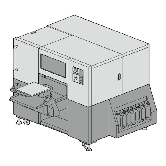
Garment printer
Hide thumbs
Also See for GTX600SB:
- Instruction manual (345 pages) ,
- Instruction manual (27 pages) ,
- Installation and setup (9 pages)
Advertisement
Quick Links
GTX600SB
Professional Use
GARMENT PRINTER
Setup Manual
Please be sure to read this manual before using this product.
Keep this manual in a safe place for future use.
This printer should only be used by operators who are
appropriately trained in its safe operation.
Please be sure to read "SAFETY INSTRUCTIONS" before use.
Table of contents
10
14
37
41
45
Advertisement

Related Manuals for Brother GTX600SB


Summary of Contents for Brother GTX600SB
-
Page 1: Table Of Contents
This printer should only be used by operators who are appropriately trained in its safe operation. Table of contents Please be sure to read "SAFETY INSTRUCTIONS" before use. Installation Setup of the printer Connection to a PC Adjustment GTX600SB Professional Use Maintenance list GARMENT PRINTER Setup Manual... - Page 2 SAFETY INSTRUCTIONS Thank you very much for buying a BROTHER printer. Before The instructions which follow this term using your new printer, please read the "SAFETY indicate situations where failure to follow IMPORTANT INSTRUCTIONS" and handling instructions carefully. the instructions may result in damage to property.
- Page 3 Water dripping from the printer may cause fire, To prevent accidents and problems, do not modify electric shocks, or problems. the machine yourself. Brother will not be held responsible for any accidents or problems resulting from modifications made to the machine.
- Page 4 SAFETY INSTRUCTIONS Unplug the printer and contact the dealer where WARNING you purchased the printer or a trained technician if the printer topples over. If you continue to use it, it Printing may result in fire or electric shocks or poor printing quality.
- Page 5 When replacing parts and installing optional Maintenance accessories, be sure to use only genuine Brother parts. Brother will not be held responsible for any Be careful not to pinch your fingers when closing accidents or problems resulting from the use of each cover.
- Page 6 ® marks or TM marks are not used. printer may be mechanically and electrically Brother logo is registered trademark of Brother Industries, Ltd. damaged. Apple, Macintosh, Mac OS, iOS, OS X, macOS, Safari, iPad, Ensure there is adequate space left in front of the iPhone, iPod and iPod touch are the trademarks or registered trademarks of Apple Inc.
- Page 7 3. Warning labels This printer has the following warning labels displayed on it. Follow the precautions given on each warning label for your work. When the label is peeled off or illegible, contact the place of purchase. 1 5 Waste water Ink bottle Waste ink tank...
- Page 8 SAFETY INSTRUCTIONS...
- Page 9 <When you dispose of the machine> 3) Pickup the Lithium Battery (1) to the direction of the arrow. Required Tools Phillips screwdriver: M3 to M5 Disassembling 1) Remove the Cover of BACK SIDE bottom center. Note based on California law (USA) on the use and handling of Perchlorate This product contains a CR Coin Lithium Battery which contains Perchlorate Material –...
-
Page 10: Installation
Installation Checking the installation site 23.6 in. (60 cm) or more The following environmental requirements should be met: Environment Temperature Humidity 0°C (32°F) to Humidity (%) 40°C (104°F) 31.5 in. (80 cm) 20 % to 85 % or more (no condensation) Working 10°C (50°F) to... - Page 11 Unpacking When installing the printer, avoid any place that presents direct sunlight or a large amount of dust. The size is 73.6 in. (width) x 75.6 in. (depth) x 57.5 in. (height) (187 cm (width) x 192 cm (depth) x 146 cm (height)). The main unit weighs 690 kg (1521 lb).
- Page 12 Installation ① Main tank cover Check the supplied accessories. ② Main tank cover installation screw (M4) ×2 ③ Hole cap (black) ×2 ① ② ③ ④ ⑤ ⑥ ④ Print switch unit ×2 ⑤ Print switch cover installation screw ×8 ⑥...
- Page 13 Transporting the printer X1122 There is a label on the back of the printer that indicates the insertion slot. X1120 CAUTION The printer has a dimension of 73.6 in. (width) × 75.6 in. (depth) × 57.5 in. (height) (187 cm (width) × 192 cm (depth) ×...
-
Page 14: Setup Of The Printer
Setup of the printer Removing the protection materials Remove all the tapes and sheets. Main body Cushioning material between tanks... - Page 15 Maintenance Keyhole Unlock and open the upper left side cover. Remove the cap fixing plate with a flat-blade screwdriver.
- Page 16 Setup of the printer Mount the supplied accessories according to the following procedures. Main tank cover Keep the cap fixing plate mounted onto the maintenance unit. Remove the band and then remove the tube. Keep the supplied cam fixing pins mounted onto the maintenance unit and close the cover.
- Page 17 Pull out the main tank unit until it comes in contact with the Remove the two screws on the side. stopper. The removed screws are required when transporting the printer again. TIPS Main tank cover installation screw (M4) Temporarily tighten the supplied two main tank cover installation screws (M4).
- Page 18 Setup of the printer ② ① Align the bands provided for the tank caps so that the bands Insert the main tank cover firmly to direction ② and securely face the front. Then lift and slide the main tank cover in the tighten the two main tank cover installation screws (M4) that direction of ①...
- Page 19 Print switch Install the print switches on the proper side. The side with the hole faces the platen side to allow IMPORTANT the wire harness to passed through it. Print switch unit installation screw Check the left and right sides. Secure the print switch unit with the four print switch unit installation screws from the bottom of the main unit.
- Page 20 Setup of the printer Connect the two connectors and insert the harness inside. Print switch cover Print switch cover installation screw Mount and tighten the cover with the four print switch cover installation screws. Similarly, connect the other print switch unit. Position the print switch cover in front of the IMPORTANT frame and tighten the screws.
- Page 21 Waste ink tank and waste water tank Waste Waste water tank ink tank X1073 Check the direction of the tank hole and install the tank as Open the lower left side cover. shown on the label. Insert each tube into the tank and close the cover after installation.
- Page 22 Setup of the printer Humidifier pipe Keyhole Humidifier pipe Unlock and open the right-hand-side cover. Attach the humidifier pipe. Attach the humidifier pipe so that its tab fits into the groove on the pipe on the printer. TIPS...
- Page 23 Carriage belt tension adjustment Adjust the carriage belt tension at a room IMPORTANT temperature of 18°C to 30°C. Turn off the power. Keyhole Loosen the two bolts on the carriage belt holder. Unlock and open the right-hand-side cover. Loosen the two bolts until there is a gap IMPORTANT between each bolt’s face and the part.
- Page 24 Setup of the printer About the water used If supplying from a water pipe Use pure water. If non-pure water, such as tap water, is used, white powdery impurities will adhere to the inside of the unit, causing damage to the printer and heads.
- Page 25 If supplying from a tank Be sure to mount a cable cover with sufficient strength to the tube. Water will not be supplied and may leak to the floor if the tube is broken or cut off. Lay the tube so that the bending radius is 2.0 in. (5 cm) or more.
- Page 26 Setup of the printer Connect the humidifier water supply tube. *Remove this tube in the case of using a tube with a connection Loosen the two screws on the lower left-hand-side cover on the diameter of 4 mm. right-hand side of the printer. Insert the humidifier water supply tube into the outlet marked WATER.
- Page 27 Disconnecting the humidifier water supply tube Supplying from a tank Release ring Press to unlock Humidifier filter Press the release ring to unlock and pull out the tube. Install the humidifier filter.
- Page 28 Setup of the printer Disconnecting the tube or plug Plug Release ring Press to unlock Lever Press the release ring to unlock and pull out the plug. When using two or more printers, unplug and insert the tube. Close Open TIPS Be careful when unplugging, as the plug can be stiff.
- Page 29 Turning on the power Adjusting the levelness Press to move the platen to the front. Power switch Power cord insertion port Apply a level to the center of the platen. Insert the power cord into the power cord insertion port and plug the cord into an electrical outlet.
- Page 30 Setup of the printer Refilling the ink and cleaning solution Turn ON the power of the printer and perform the operation while the printer is in Standby mode. If there is new firmware, update the printer. CAUTION Be sure to wear a pair of plastic gloves and protective glasses while refilling the ink.
- Page 31 3) Refill the ink and cleaning solution. Take care not to lose the IC sticks that come IMPORTANT standard with the refill ink bottle and cleaning When refilling, exercise care not to fill past the solution bottle. graduation line above 6. Refill white ink and Store the respective IC sticks by attaching them IMPORTANT cleaning solution past the graduation line under...
- Page 32 Setup of the printer Mounting the wiper -> [Maintenance] -> [Maintenance Part Clean/Replace] -> [Replace maintenance unit parts] -> Right-hand- side cover Keyhole Left-hand- side cover X1123 Hold the latch of the wiper on the left-hand side and insert the wiper into the maintenance unit from the right-hand side.
- Page 33 Mounting the flushing foam After this assembly process is completed, make sure that no flushing foam extends off the outboard end portions of the maintenance unit. IMPORTANT If it sticks out of the end portions, it may interfere with any nozzles and may result in non-ejection of ink-jet droplets.
- Page 34 Setup of the printer Mounting the carriage foam Keyhole Foam pad Unlock and open the right-hand-side cover. Move the carriage foam along the sliding surface of the guide Foam guide in the direction of the arrow until the carriage foam comes in contact with the foam pad (two places).
- Page 35 Foam lower surface Foam pad Nozzle surface Make sure that the nozzle surface is below the lower surface of Rotate the carriage foam and attach it to the magnet. the foam, close the cover, and follow the screen to return the Make sure the carriage foam is not on the foam pad.
- Page 36 Setup of the printer Configuring the language Perform the operation while the printer is in Standby mode. -> [Language] -> Select your language -> 2) Press the power button to turn off the power. Installing the ink Turn ON the power of the printer and perform the operation while the printer is in Standby mode.
-
Page 37: Connection To A Pc
Connection to a PC Although the description of this section is based on operation with Windows, you can also use Macintosh. For details, refer to the Instruction Manual. TIPS Installing the driver Connecting via LAN 1) Download the ZIP file from our website and unzip the file. Assignment of printer static IP address 2) Double-click on "setup.exe"... - Page 38 Connection to a PC If [Manual setting] is selected: Installing the network print driver 1) Connect the printer and PC to a network using LAN cables 3) Press to select the position to be changed. and turn the printer power ON. 4) Press to set the value.
- Page 39 4) [The printer that I want isn't listed] -> Select [Add a local 6) Enter the static IP address of the printer into [Type a printer printer or network printer with manual settings] -> [Next]. hostname or IP address] -> Make sure that the check box of [Query the printer and automatically select the driver to use] is checked ->...
- Page 40 11) Enter the [Printer name] -> [Next]. [Queue Name] of [LPR Settings] -> [OK] -> [Next]. 12) Select [Do not share this printer] -> [Next] -> [Finish]. 9) From [Manufacturer], select [Brother] -> From [Printer], select [Brother GTX-6 Extra Colors ORGR] -> [Next].
-
Page 41: Adjustment
Adjustment Checking the nozzle check pattern 1) Make sure that the platen height is set at the "A" position. 4) When printing is finished, and the printer returns to Standby mode, set a piece of black paper or transparent sheet (such Use a platen sized 14 in. - Page 42 Adjustment 8) Check the printed results for both nozzle check prints and determine if there is a problem. If missing nozzles are found as indicated by the arrows below, there is a problem concerning the firing of the print heads. Even if the lines of the white-side printed result are light, since white ink is fired from more than one nozzle on the same place, the quality is not...
- Page 43 1) Connect the PC and printer via a LAN cable, and start While the printer is in Standby mode, press -> Select "Brother GTX-6 Extra Colors ORGR Tools" -> "GTX-6 Extra Colors ORGR Maintenance" on the PC. the head with the problem -> Press...
- Page 44 Adjustment Menu name Things to prepare [Initial settings after ― head replacement] [Color adjustments between color/ORGR White paper heads] Black paper or transparent [Firing Adjustment] sheet (such as OHP sheet) White paper [Position adjustment for Black paper or transparent the 2 heads of the same sheet (such as OHP sheet) color] White paper...
-
Page 45: Maintenance List
Maintenance list To maintain the printing quality and use the printer for a longer time, the following maintenance is needed. For details, refer to the Instruction Manual. Error / Maintenance timing Description Warning display Before printing Print out of the nozzle check pattern (checking on the print heads) ―... - Page 46 *Please note that the contents of this manual may differ slightly from the actual product purchased as a result of product improvements. https://www.brother.com/ 1-5, Kitajizoyama, Noda-cho, Kariya 448-0803, Japan. © 2022 Brother Industries, Ltd. All Rights Reserved. GT60SB SC7329-001 EN This is the original instructions.
Need help?
Do you have a question about the GTX600SB and is the answer not in the manual?
Questions and answers