
Related Manuals for EM Acoustics M-C15


Summary of Contents for EM Acoustics M-C15
- Page 1 M-C15 two-way passive coaxial stage monitor Product User Manual v2 November 2019 L O U D S P E A K E R S D E F I N E D...
-
Page 2: Table Of Contents
5.0 – Rigging & Mounting Options ......................12 5.1 – M-C15 Cabinet Overview......................12 5.2 – Using the FC-MC15 ........................13 5.3 – Using the M-C15 on a loudspeaker stand ................13 5.4 – Using the IB-MC15 ......................... 14 6.0 – Powering the System ........................15 6.1 - Amplifier and Processing Requirements ................ - Page 3 6.4.1 - Cable Length and Specification ..................19 6.4.2 – Crossover Cable Use ......................19 7.0 – Servicing Information ........................20 7.1 – M-C15: Removing the grille ....................... 20 7.2 – M-C15: Removing the drive unit....................21 Appendix A – Technical Specifications ....................22 M-C15 coaxial passive stage monitor ....................
-
Page 4: Declaration Of Conformity
The packaging supplied with this product is recyclable. Please retain all packaging, however if disposing of this packaging please ensure that you comply with local recycling regulations. These products also all comply to the RoHS Directive 2002/95/EC. M-C15 User Manual v2 November 2019... -
Page 5: Introduction
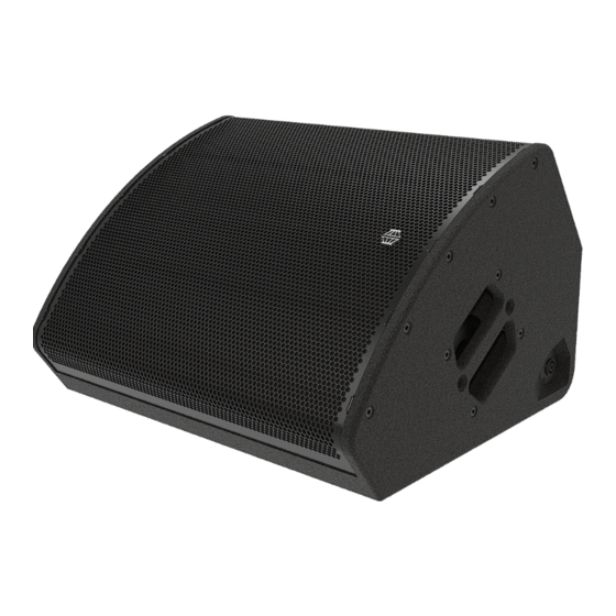
EM Acoustics representative. The M-C15 is a compact, passive 2-way coaxial stage monitor, intended to be not just an exacting stage monitor, but through additional features to be a useful FOH loudspeaker as well. -
Page 6: M-C15 & Accessories
NET/SHIPPING WEIGHT: FC-MC15 Touring flying cradle The FC-MC15 is a simple and effective means of mounting the M-C15 in temporary applications. It is secured to the cabinet by means of threaded locking knobs into the top of the loudspeaker to mount it in a portrait format. A single 13mm diameter hole is provided for attachment in installation or via a hook clamp or similar. -
Page 7: Rotating The Hf Waveguide
Page 7 of 27 2.1 – Rotating the HF waveguide The high frequency waveguide of the M-C15 can be easily rotated to provide appropriate dispersion in both portrait and landscape formats. By default, the M-C15 ships from the factory with the dispersion pattern 40° horizontal x 60°... -
Page 8: Simulation
Tutorials for Ease Focus 3 are available from with the application itself. For training on the design and implementation of M-C15 monitors including the specific use of Ease Focus 3, please contact your local distributor. -
Page 9: Safety Considerations
General Considerations in use Loudspeaker systems are potentially dangerous objects if used incorrectly. Please ensure that you read this section fully, and contact EM Acoustics or your local dealer should you be in any doubt over correct operation procedures. Personal Injury Never stand in the immediate vicinity of loudspeakers when in use at high level. -
Page 10: Ground Stacking
EM Acoustics is in no way liable for any loss, damage or injury caused by such practice. Do not modify or alter the M-C15 loudspeaker or accessories, nor use them in any way other than that described in this manual. Rigging components supplied with the M-C15 are in no way interchangeable and should not be used as such. -
Page 11: Secondary Safeties
In most cases, annual independent tests & inspections carried out by a suitably approved and qualified inspector will be required. EM Acoustics recommends detailed logbooks be kept of all inspections and load tests to ensure an accurate record is kept of the testing for each EM Acoustics rigging accessory. -
Page 12: Rigging & Mounting Options
Page 12 of 27 5.0 – Rigging & Mounting Options 5.1 – M-C15 Cabinet Overview Side M8 mounting point Handle Polemount M-C15 User Manual v2 November 2019... -
Page 13: Using The Fc-Mc15
5.3 – Using the M-C15 on a loudspeaker stand Concealed within the handle on the right-hand side of the M-C15 enclosure is a standard 35mm polemount. By turning the loudspeaker on its end, it can be placed onto a loudspeaker stand when using as a FOH loudspeaker. -
Page 14: Using The Ib-Mc15
Once the desired angle is arrived at, securely tighten all four bolts to lock the loudspeaker in place. Multiple attachment holes are provided to secure the IB-MC15 to walls or ceilings in an installation environment. Always ensure that a secondary safety is used when suspending any loudspeaker. M-C15 User Manual v2 November 2019... -
Page 15: Powering The System
Page 15 of 27 6.0 – Powering the System The M-C15 can be powered from any amplifier & DSP combinations with the relevant high & low pass filter, and limiter settings. However, due to the self-contained nature of the package, the use of DQ Series advanced system amplifiers is highly recommended. The... -
Page 16: Amplifier Requirements
All of the DQ Series advanced system amplifiers can be used to power the M-C15. The following table shows the maximum number of M-C15 that can be connected per... -
Page 17: Presets And Settings
6.2 - Presets and Settings 6.2.1 – Standard M-C15 Preset When used with a DQ Series amplifier M-C15 loudspeakers require only a single amplifier channel, and as such the preset recalled will only require one output from your DQ Series amplifier. -
Page 18: Use With The Dq Series Advanced System Amplifiers
Page 18 of 27 6.3 - Use with the DQ Series Advanced System Amplifiers The M-C15 will perform best when using DQ Series advanced system amplifiers, as not only are they state-of-the-art amplifiers, but the onboard DSP provides appropriate high/low pass filter settings and limiters to get the best from your subwoofers. -
Page 19: System Connectivity
Because pins 2+/2- are linked through inside all EM Acoustics loudspeakers, using a 4-core cable to one loudspeaker (carrying two different signals) allows a crossover cable to be used to link out of the first loudspeaker into another, thereby feeding it from a separate signal. -
Page 20: Servicing Information
To replace the grille, position the grille on the front of the M-C15 and ensure the threaded fittings on the grille are lined up with the mounting holes – gentle pressure may be required. Replace all of the M6x30 countersunk socket screws and ensure they are all are started in their threads before beginning to tighten. -
Page 21: M-C15: Removing The Drive Unit
Page 21 of 27 7.2 – M-C15: Removing the drive unit TOOLS REQUIRED: 4mm & 5mm Allen keys Complete step 7.1 above to remove the grille. Using a 5mm Allen key, undo the eight M6x30 socket cap bolts holding the drive unit in place. Ensure you also collect the spring washers. -
Page 22: Appendix A - Technical Specifications
Page 22 of 27 Appendix A – Technical Specifications M-C15 coaxial passive stage monitor Dimensions (HxWxD): 359 x 570 x 505mm (14.1” x 22.4” x 19.9”) Net/Shipping Weight: 25kg/27.3kg (55/60lbs) Frequency Response (+/- 3dB) 55Hz – 20kHz Dispersion 40° H x 60° V (monitor orientation) 60°... -
Page 23: Appendix B - Technical Drawings
Page 23 of 27 Appendix B – Technical Drawings M-C15 User Manual v2 November 2019... - Page 24 Page 24 of 27 M-C15 User Manual v2 November 2019...
- Page 25 Page 25 of 27 M-C15 User Manual v2 November 2019...
-
Page 26: Appendix C - Spare Parts List
Appendix C – Spare Parts List Order Code Description 01A502 CAD-1501 replacement 15”/1.3” coaxial drive unit 01D013 RD-C301 replacement 3” diaphragm for CAD-1501 04A034 RFG-MC15 replacement grille/fabric for M-C15 07A036 PX-MC15 replacement passive crossover assembly for M-C15 M-C15 User Manual v2 November 2019... -
Page 27: Appendix D - Warranty Information
Serial numbers must be quoted in all correspondence relating to the claim. EM Acoustics or its representatives are in no way liable for any loss or damage in transit, and hence it is recommended that the sender insure the shipment. EM Acoustics will pay for return freight should the repair be covered under warranty.
Need help?
Do you have a question about the M-C15 and is the answer not in the manual?
Questions and answers