Table of Contents
Advertisement
Quick Links
Instruction Manual
D104143X012
Fisher
CL600 Control-Disk
™
Contents
. . . . . . . . . . . . . . . . . . . . . . . . . . . . . . . . . . .
. . . . . . . . . . . . . . . . . . . . . . . . . . . .
. . . . . . . . . . . . . . . . . . . . . . . . . . . . . . . .
. . . . . . . . . . . . . . . . . . . . . . . . . . . . . .
. . . . . . . . . . . . . . . . . . . . . . . . . . . . . . . . . .
. . . . . . . . . . . . . . . . . . . . . . . . . . . . . . . .
. . . . . . . . . . . . . . . . . . . . . . . . .
. . . . . . . . . . . . . . . . . . . . . . . . . . . . . . . .
. . . . . . . . . . . . . . . . . . . . . . . . . . . . . . . . . . .
. . . . . . . . . . . . . . . . . . . . . . . . . . . . . . . . . . .
Introduction
Scope of Manual
This instruction manual includes installation, maintenance, and parts information for the Fisher CL600 Control-Disk
valve, NPS 3 through NPS 24 (figure 1). Refer to separate instruction manuals for information covering the power
actuator and accessories.
Do not install, operate, or maintain a CL600 Control-Disk valve without being fully trained and qualified in valve,
actuator, and accessory installation, operation, and maintenance. To avoid personal injury or property damage, it is
important to carefully read, understand, and follow all the contents of this manual, including all safety cautions and
warnings. If you have any questions about these instructions, contact your
Description
The Fisher CL600 Control-Disk valve maintains tight shutoff, and can be specified for a wide range of pressure and
temperature conditions.
The CL600 Control-Disk valve is available in a lugged or double flanged body design. A splined shaft can combine with
a variety of spring-and-diaphragm or pneumatic piston actuators. A keyed shaft option is available for larger sizes and
can combine with a variety of pneumatic piston actuators. These combinations help make the CL600 Control-Disk
valve a reliable rotary control valve for control applications in the process industries.
www.Fisher.com
. . . . . . . . . . . . . . . . . . . . . . . . .
. . . . . . . . . . . . . . . . . . . . . . .
. . . . . . . . . . . . .
. . . . . . . . .
Rotary Valve
™
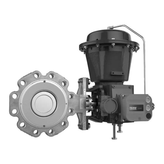
Figure 1. Fisher CL600 Control-Disk Valve with 2052
Actuator and DVC6200 Digital Valve Controller
1
1
1
2
2
4
10
11
14
16
22
23
23
24
X0955-1
Emerson sales office
CL600 Control-Disk Valve
January 2019
before proceeding.
Advertisement
Table of Contents

Related Manuals for Emerson Fisher Control-Disk CL600


Summary of Contents for Emerson Fisher Control-Disk CL600
-
Page 1: Table Of Contents
To avoid personal injury or property damage, it is important to carefully read, understand, and follow all the contents of this manual, including all safety cautions and warnings. If you have any questions about these instructions, contact your Emerson sales office before proceeding. Description The Fisher CL600 Control-Disk valve maintains tight shutoff, and can be specified for a wide range of pressure and temperature conditions. -
Page 2: Specifications
Disk Rotation Clockwise (CW) to close Educational Services For information on available courses for Fisher CL600 Control-Disk valves, as well as a variety of other products, contact: Emerson Automation Solutions Educational Services - Registration Phone: 1-641-754-3771 or 1-800-338-8158 E-mail: education@emerson.com emerson.com/fishervalvetraining Table 2. - Page 3 Instruction Manual CL600 Control-Disk Valve D104143X012 January 2019 Figure 2. Available Seal Configurations BACK-UP ANTI-EXTRUSION BACK-UP BODY BODY ANTI-EXTRUSION RING RING RING RING RETAINING SEAL RING RING SEAL RING RETAINING HIGH PRESSURE RESILIENT RING AT SHUTOFF INSERT VALVE DISK VALVE DISK HIGH PRESSURE AT SHUTOFF SOFT SEAL WITH...
-
Page 4: Installation
-198 to 371 -325 to 700 1. The maximum temperature for a standard of the CL600 Control-Disk valve is 538_C (1000_F). Contact your Emerson sales office for use in higher temperature applications 2. For use with soft seal only. Installation Key numbers in this procedure are shown in figures 13, 14, and 15 unless otherwise indicated. - Page 5 Emerson sales office. The maximum allowable inlet pressures for steel and stainless steel valve bodies are consistent with the pressure‐temperature ratings shown in table 1, except where further limited by the trim and packing material...
- Page 6 Instruction Manual CL600 Control-Disk Valve January 2019 D104143X012 Lifting Guidelines Threaded holes for lifting are standard on the NPS 6 - 24 valve bodies. It is required that swivel hoists rings be used to lift the valve or valve and actuator assembly. An eyebolt cannot accommodate all lifting angles required to install or maintain the valve.
- Page 7 Instruction Manual CL600 Control-Disk Valve D104143X012 January 2019 Figure 3. Lugged Valve Body Lifting Thread Locations (NPS 10 shown) LIFTING THREAD LIFTING THREAD Notes: Holes on opposite side are identical. NPS 10-24 only. Table 5. Lugged Valve Body Lifting Thread Information THREAD SIZE THREAD DEPTH NUMBER OF THREADED...
- Page 8 Instruction Manual CL600 Control-Disk Valve January 2019 D104143X012 Table 6. Double Flange Valve Body Lifting Thread Information THREAD SIZE THREAD DEPTH NUMBER OF THREADED VALVE SIZE, NPS HOLES Inches Inches 3/8-16 14.2 0.56 1/2-13 19.1 0.75 3/4-10 41.9 1.65 44.5 1.75 1-1/4-7 2.72...
- Page 9 Instruction Manual CL600 Control-Disk Valve D104143X012 January 2019 Figure 5. Stud Bolts for Installation (also see table 7) LUGGED VALVE BODY LUGGED VALVE BODY WITH THREADED HOLES WITH THROUGH HOLES Figure 6. Double Flange Stud Bolts for Installation (also see table 8) DOUBLE FLANGE VALVE BODY DOUBLE FLANGE VALVE BODY WITH THREADED HOLES...
-
Page 10: Maintenance
Instruction Manual CL600 Control-Disk Valve January 2019 D104143X012 shaft to the valve body for hazardous area service. For oxygen service applications, provide alternate shaft‐to‐valve body bonding according to the following step. 9. For oxygen service applications, attach the bonding strap assembly (key 34, figure 7) to the shaft with the clamp (key 33, figure 7), and connect the other end of the bonding strap assembly to the valve body with the cap screw (key 31). -
Page 11: Packing Maintenance
Instruction Manual CL600 Control-Disk Valve D104143X012 January 2019 D Use bypass valves or completely shut off the process to isolate the valve from process pressure. Relieve process pressure on both sides of the valve. Drain the process media from both sides of the valve. D Vent the power actuator loading pressure and relieve any spring precompression. - Page 12 Instruction Manual CL600 Control-Disk Valve January 2019 D104143X012 Stopping Leakage For valves with PTFE or graphite packing: CAUTION Tighten the packing flange only enough to prevent shaft leakage. Excessive tightening will only accelerate wear of the packing and could produce higher torques on the valve. Leakage around the packing followers can be stopped by tightening the packing flange nuts (key 27).
- Page 13 Instruction Manual CL600 Control-Disk Valve D104143X012 January 2019 For valves with PTFE or graphite packing: Key numbers in this procedure are shown in figures 13, 14, and 15 unless otherwise indicated. 1. Isolate the control valve from the line pressure, release pressure from both sides of the valve body, and drain the process media from both sides of the valve.
-
Page 14: Replacing The Seal Ring Assembly
Instruction Manual CL600 Control-Disk Valve January 2019 D104143X012 For valves with ENVIRO‐SEAL packing systems: 1. Isolate the control valve from the line pressure, release pressure from both sides of the valve body, and drain the process media from both sides of the valve. If using a power actuator, also shutoff all pressure lines to the power actuator, release all pressure from the actuator. - Page 15 Instruction Manual CL600 Control-Disk Valve D104143X012 January 2019 CAUTION Damage to the disk (key 6) may occur if the disk is not closed when the valve is being removed from the pipeline. If necessary, apply operating pressure to the actuator temporarily to retain the disk in the closed position while removing the valve from the pipeline.
-
Page 16: Replacing The Disk, Shafts, Or Bearings
Instruction Manual CL600 Control-Disk Valve January 2019 D104143X012 CAUTION The retainer gasket (key 18) is a thin graphite material. Take care to avoid damaging the gasket during handling. 5. When the seal and gasket are seated, re-install the seal retainer (key 16) and screws (key 17). Tighten the retainer screws just enough to eliminate vertical movement of the seal retainer. - Page 17 Instruction Manual CL600 Control-Disk Valve D104143X012 January 2019 Table 10. Follower Shaft Internal Threads VALVE SIZE, NPS THREAD SIZE 10 - 24 1/4 - 20 3/8 - 16 1/2 - 13 5/8 - 11 1. Isolate the control valve from the line pressure, release pressure from both sides of the valve body, and drain the process media from both sides of the valve.
- Page 18 Instruction Manual CL600 Control-Disk Valve January 2019 D104143X012 WARNING Once the shafts have been removed in the following step, the disk may fall from the valve body. To avoid personal injury and disk damage, support the disk to prevent it from falling as the shafts are being removed. 6.
- Page 19 Instruction Manual CL600 Control-Disk Valve D104143X012 January 2019 Figure 10. Disk Orientation for Pin Removal and Soft Seal Installation JOURNAL DISK VALVE BODY BEARING THRUST BEARING DRIVE SHAFT CAUTION To avoid possible product damage, ensure the NPS 3, 4, and 6 thrust bearings are oriented correctly when installing in the following procedure.
- Page 20 Instruction Manual CL600 Control-Disk Valve January 2019 D104143X012 Figure 11. Orientation of NPS 3, 4, and 6 Thrust Bearings 1. If new bearings (keys 14 and 15) are required, install them in the valve body. Install the journal bearings (key 14) before installing the thrust bearing (key 15).
- Page 21 Instruction Manual CL600 Control-Disk Valve D104143X012 January 2019 CAUTION Once the final preload torque is applied, do not loosen or remove the blind flange nuts (key 5). If nut removal is necessary, a new gasket is required. Soft Seal Installation 1.
-
Page 22: Actuator Mounting
Instruction Manual CL600 Control-Disk Valve January 2019 D104143X012 2. Place the retainer gasket (key 18) in the groove in the valve body. 3. Attach the seal retainer (key 16) to the valve body and tighten the retainer screws (key 17) just enough to eliminate the vertical movement of the retainer. -
Page 23: Parts Ordering
When ordering replacement parts, also specify the key number, part name, desired material, using the Parts List. WARNING Use only genuine Fisher replacement parts. Components that are not supplied by Emerson Automation Solutions should not, under any circumstances, be used in any Fisher valve, because they may void your warranty, might adversely affect the performance of the valve, and could cause personal injury and property damage. -
Page 24: Parts List
20* O-ring, PTFE Seal 21* Packing Box Ring 22* Packing Set Note 23 Anti Blowout Ring Contact your Emerson sales office for part ordering information. 24 Packing Follower 25 Packing Flange 26 Packing Stud (NPS 3-8, 2 req'd, NPS 10-24, 4 req'd) 27... - Page 25 Instruction Manual CL600 Control-Disk Valve D104143X012 January 2019 Figure 13. Fisher CL600 Control-Disk, NPS 3-6, CL600 Valve Assembly NOTES: USE ONLY WITH PHOENIX III AND SOFT SEAL USE ONLY WITH NPS 3 SOFT SEAL AND PHOENIX III SEAL PARTS NOT SHOWN: 32, 33, 34, 37, 38, 39, 41, 42 GE72059-A...
- Page 26 Instruction Manual CL600 Control-Disk Valve January 2019 D104143X012 Figure 14. Fisher CL600 Control-Disk, NPS 8, CL600 Valve Assembly NOTES: USE ONLY WITH PHOENIX III AND SOFT SEAL PARTS NOT SHOWN: 32, 33, 34, 37, 38, 39, 41, 42 GE72101-A...
- Page 27 Instruction Manual CL600 Control-Disk Valve D104143X012 January 2019 Figure 15. Fisher CL600 Control-Disk, NPS 10-24, CL600 Valve Assembly VIEW A SCALE 1:125 NPS 14-24 NOTES: USE ONLY WITH PHOENIX III AND SOFT SEAL VIEW A PARTS NOT SHOWN: 32, 33, 34, 37, 38, 39, 41, 42 GE72089-A...
- Page 28 Fisher, Control-Disk, and ENVIRO-SEAL are marks owned by one of the companies in the Emerson Automation Solutions business unit of Emerson Electric Co. Emerson Automation Solutions, Emerson, and the Emerson logo are trademarks and service marks of Emerson Electric Co. All other marks are the property of their respective owners.
Need help?
Do you have a question about the Fisher Control-Disk CL600 and is the answer not in the manual?
Questions and answers