Anritsu MS27201A User Manual
High-performance rf remote spectrum monitor
Hide thumbs
Also See for MS27201A:
- User manual (262 pages) ,
- Measurement manual (172 pages) ,
- Measurement manual (152 pages)
Table of Contents

Related Manuals for Anritsu MS27201A


Summary of Contents for Anritsu MS27201A
- Page 1 User Guide Remote Spectrum Monitor MS27201A High-Performance RF Spectrum Monitor Anritsu Company Part Number: 10580-00480 490 Jarvis Drive Revision: B Morgan Hill, CA 95037-2809 Published: July 2023 Copyright 2023 Anritsu Company...
- Page 2 Anritsu Company. Export Management The Anritsu products identified herein and their respective manuals may require an Export License or approval by the government of the product country of origin for re-export from your country. Before you export these products or any of their manuals, please contact Anritsu Company to confirm whether or not these items are export-controlled.
-
Page 3: Table Of Contents
Connecting to the MS27201A or Localhost ........ - Page 4 Importing Software License ........... B-1 Contents-2 PN: 10580-00480 Rev. B MS27201A UG...
-
Page 5: Chapter 1-General Information
Chapter 1 — General Information Introduction The MS27201A Remote Spectrum Monitor (RSM) User Guide is part of a set of manuals that cover all of the instrument functions and their use. This manual covers the instrument overview, system functions, and other common features, along with a brief guide to basic measurement concepts and setups. -
Page 6: Document Conventions
Document Conventions The following conventions are used throughout the MS27201A documentation set. Instrument Identification When identifying a frequency option for the MS27201A, that option number is appended after the model number; example: MS27201A-0709. User Interface The MS27201A user interface consists of menus, buttons, toolbars, and dialog boxes. -
Page 7: Available Options
LTE FDD/TDD Measurements (requires GNSS Receiver MS27201A-0031) MS27201A-0888 5GNR Downlink Measurements (requires GNSS Receiver MS27201A-0031) MS27201A-xxxx-0097 Accredited Calibration to ISO17025 and ANSI/NCSL Z540-1 (xxxx is the frequency Option number) Standard Calibration to ISO17025 and ANSI/NCSL Z540-1 (xxxx is the frequency Option... -
Page 8: Instrument Care And Preventive Maintenance
If a wrench is needed, use an open-end wrench to keep the connector body from turning while loosening with a second wrench. Complete the disconnection by hand, turning only the connector nut. Pull the connectors straight apart without twisting or bending. PN: 10580-00480 Rev. B MS27201A UG... -
Page 9: Esd Caution
Anritsu recommends annual calibration and performance verification by local Anritsu service centers. Contacting Anritsu for Sales and Service To contact Anritsu, visit the following URL and select the services in your region: http://www.anritsu.com/contact-us MS27201A UG PN: 10580-00480 Rev. B... - Page 10 1-5 Contacting Anritsu for Sales and Service General Information PN: 10580-00480 Rev. B MS27201A UG...
-
Page 11: Chapter 2-Instrument Overview
(PN: 10580-00447). Connector Panels The MS27201A Remote Spectrum Monitor uses two connector panels to provide for all physical IO. These panels use a variety of connector types intended for their purpose. RF Connectors The main RF input connector can be Type N or Type K, depending on the frequency option that is installed. -
Page 12: Front Panel
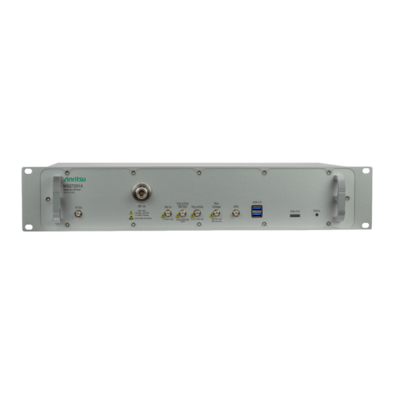
2-2 Connector Panels Instrument Overview Front Panel Figure 2-1 shows the front connector panel on the MS27201A. Figure 2-1. Front Panel Connectors 1. RF In Port This is a 50 ruggedized connector of the following: • Type N female with options 709 and 720 •... -
Page 13: Rear Panel
RF output level is –4 dBm with a 10 MHz, –20 dBm input, and with 0 dB input attenuation and preamp off. The spectrum can be inverted in certain RF input bands. Rear Panel Figure 2-2 shows the real connector panel on the MS27201A. Figure 2-2. Real Panel Connectors 1. External Power This is a 2.5 mm by 5.5 mm barrel connector, 14-16 VDC, 5 A, center positive, used to power the instrument. -
Page 14: Turning On The Ms27201A Rsm
Turning On the MS27201A RSM The Anritsu MS27201A RSM is operated from a 15 VDC source connected to the rear panel. This can be achieved with either the Anritsu AC-DC adapter or the automotive power adapter, which can be purchased as an optional accessory. -
Page 15: Vision Monitor
• 8 GB RAM • Windows 10, 64-bit • 1 GB disk space • Open GL (ES) 2.0 support • Display resolution 1280 x 800 • Ethernet cable (for connecting to an MS27201A instrument) MS27201A UG PN: 10580-00480 Rev. B... -
Page 16: Installation
Instrument Overview Installation Download the MS27201A software from the product page: http://www.anritsu.com/en-US/test-measurement/products/ms2720xa Launch the MS27201A executable file and follow the on-screen instructions after selecting YES on the User Account Control dialog box. Figure 2-3. MS27201A Installation PN: 10580-00480 Rev. B... -
Page 17: Connecting To The Ms27201A Or Localhost
10 seconds. Insert the USB memory device onto a PC, then open the ip.txt file and copy the IP address in the HOSTNAME/IP ADDRESS field on the MS27201A software. Otherwise use the static IP address (10.0.0.2) that is shipped with the unit. -
Page 18: Gui Overview
Instrument Overview GUI Overview The MS27201A Remote Spectrum Monitor software controls all instrument functions. The software runs on a user-supplied PC. The figure below identifies the main display areas, which are each described in more detail later in this chapter. -
Page 19: Common Gui Controls
Refer to Section 2-16 “Software Update” on page 2-47. The local host icon is displayed only on the MS27201A PC application when connected to the localhost instead of an instrument. The icon is not functional. Refer to “MS27201A PC Software” on page 2-4. -
Page 20: Data Entry
CANCEL will restore settings back to the state they were in before the keypad opened, even if changes from the +/- controls are already reflected in the data display. • ACCEPT to operate with the settings displayed on the keypad. Figure 2-6. Menu Keypads 2-10 PN: 10580-00480 Rev. B MS27201A UG... - Page 21 Scroll through the list and select the desired entry. Figure 2-7. Menu Selection Lists To cancel the selection, click somewhere else on the display or close the menu (X). MS27201A UG PN: 10580-00480 Rev. B 2-11...
-
Page 22: Scroll Indication
The menu can be scrolled by dragging it downward to expose the information. Figure 2-8. Scroll Indication If the display is set to another color theme, the fade effect remains the same but the color may fade Note to a dark shade. 2-12 PN: 10580-00480 Rev. B MS27201A UG... - Page 23 Use the EZ keyboard to enter frequently used text strings with a single screen tap. The EZ keyboard is initially populated with default values. Each key enters the entire string as shown on the key. For convenience, you can set an automatic Separator character to be placed between each EZ key string. MS27201A UG PN: 10580-00480 Rev. B 2-13...
- Page 24 Select the key to be edited. This will display the standard keyboard for entering a new EZ key value. Figure 2-12. On-Screen EZ Keyboard Enter the new value, then click ACCEPT to assign the new value to the EZ key, or click CANCEL. 2-14 PN: 10580-00480 Rev. B MS27201A UG...
-
Page 25: Title Bar
31). If toggled on, the GPS coordinates will also display here. 8. The right side of the instrument title bar displays the system date and time. Selecting this field opens the Date Time Settings. Figure 2-13. Title Bar MS27201A UG PN: 10580-00480 Rev. B 2-15... -
Page 26: 2-10 Selecting The Analyzer
Some measurements and views are accessed via other measurement setup menus. 9-dot icon Current Measurement Figure 2-14. Example Analyzers 2-16 PN: 10580-00480 Rev. B MS27201A UG... -
Page 27: System Menu
System Menu The System menu identifies the instrument model and serial number. HOSTNAME/IP ADDRESS: Displayed only on the MS27201A PC application. This field is used to specify the IP address or hostname of an instrument that is connected to the network. -
Page 28: Notifications
Language Settings. DATE TIME: Opens the Date Time Settings. PORT SETUP: Opens Port Setup. OPTIONS: Opens the Options Settings. ADVANCED: Opens the Advanced Settings RESET: Opens the Reset Settings. Figure 2-18. Settings Menu 2-18 PN: 10580-00480 Rev. B MS27201A UG... -
Page 29: Display Settings
But if the THEME is set to Night Vision it may be suitable for viewing in a poorly lit night time conditions. Figure 2-20. Light Color Scheme MS27201A UG PN: 10580-00480 Rev. B 2-19... - Page 30 2-12 Settings Menu Instrument Overview Figure 2-21. Black on White Color Scheme Figure 2-22. Night Vision Color Scheme 2-20 PN: 10580-00480 Rev. B MS27201A UG...
- Page 31 Select CREATE FROM FILE option to create a new shortcut from an already saved setup file. Otherwise, select CREATE FROM CURRENT option to create a shortcut of the current (trace) settings of the instrument. Enter the shortcut name which is optional, and select CONTINUE. MS27201A UG PN: 10580-00480 Rev. B 2-21...
- Page 32 Select the newly created shortcut to recall the saved setup file. To delete all the shortcuts, select SYSTEM MENU (3-line icon), go to SETTINGS menu, select DISPLAY settings and select CLEAR ALL button at the bottom right of the PC display. 2-22 PN: 10580-00480 Rev. B MS27201A UG...
-
Page 33: Network Settings
Figure 2-27. Recalled Setup File: Shortcut Button Network Settings The MS27201A uses Ethernet to communicate remotely with a controller. Most instrument functions (except power on/off) can be controlled via a network connection to a PC connected directly (with an Ethernet cross-over cable) or through a network. - Page 34 The MS27201A can be configured for Dynamic Host Configuration Protocol (DHCP), an Internet protocol that automates the process of setting IP addresses for devices that use TCP/IP, and is the most common method of configuring a device for network use.
-
Page 35: Ethernet Settings
TCP/IP connectivity requires setting up the parameters described at the beginning of this section. The following is a brief overview of how to set up a general LAN connection on the MS27201A. You may need to consult your network documentation or network administrator for assistance in Note configuring your network setup. -
Page 36: Gnss (Gps) Settings (Option 31)
Instrument Overview GNSS (GPS) Settings (Option 31) The MS27201A RSM is available with a built-in global positioning receiver feature (Option 31) that can provide latitude, longitude, altitude, and UTC timing information. This option also enhances frequency reference oscillator accuracy. When the global positioning receiver is actively locked to satellites, this information is saved with all saved measurements. - Page 37 In order to acquire data from the GPS satellites, you must have line-of-sight to the satellites, or the antenna must be placed outside with no obstructions. If no GPS is connected for at least three days, the Frequency Reference annotation reads Int Std Accy. MS27201A UG PN: 10580-00480 Rev. B 2-27...
-
Page 38: Screenshot Setup
• FILE NAMING: automatic time stamp or manual time stamp • DIRECTORY: directory path to destination folder where the file is to be saved Note Screenshots can be previewed on a web browser. Refer to “Remote Files” on page 2-37. 2-28 PN: 10580-00480 Rev. B MS27201A UG... -
Page 39: Language Settings
English language. Figure 2-31. Language Settings Select the LANGUAGE drop-down menu and select a desired display language as shown in the Figure 2-31. MS27201A UG PN: 10580-00480 Rev. B 2-29... -
Page 40: Date Time Settings
GPS time. Select Manually set to activate the MANUAL DATE TIME window. Here you can scroll to a selectable year, month, day, hour, and minute. • Time Zone: Lists the selectable time zones. 2-30 PN: 10580-00480 Rev. B MS27201A UG... -
Page 41: Port Setup
Select SETTINGS to access the settings menu, then select PORT SETUP to display the top panel bias voltage output settings. Figure 2-33. Bias Voltage Port Settings Manually set the voltage in the range of 0 V to 34 V. Toggle the bias voltage on or off. MS27201A UG PN: 10580-00480 Rev. B 2-31... - Page 42 To set PORT 1 as a reference output, toggle 10 MHz REFERENCE OUT on. Otherwise, PORT 1 can be selected as a trigger input or trigger output by using the drop-down selection. Use the drop-down selections to select PORT 2 as a trigger input or GPS 1PPS output. 2-32 PN: 10580-00480 Rev. B MS27201A UG...
-
Page 43: Options Settings
WEB to install options available on the web. Ensure that the unit is connected to the Internet. Select ENABLE OPTIONS USING FILE to install options file saved in USB memory device. Select SAVE CONFIG to export the config file to Anritsu. Figure 2-35. Options Settings... -
Page 44: Advanced Settings
Access the System menu (3-line icon in the upper left corner). Select SETTINGS to access the instrument settings menu. Select ADVANCED to display the RF Safe Mode. Toggle the ENABLE option to enable the RF SAFE MODE. Figure 2-37. Advanced Settings 2-34 PN: 10580-00480 Rev. B MS27201A UG... -
Page 45: Reset Settings
EZ names, cable and antenna lists, and log files. Other user files are not affected. RESET ALL • RESET ALL: Performs a Factory Reset as described above and deletes all user files and system files from the instrument’s internal memory. The instrument will automatically restart. MS27201A UG PN: 10580-00480 Rev. B 2-35... -
Page 46: 2-13 Files
For example: ftp://172.155.1.2 Enter the user name: ftp Enter the password: serial number of the instrument The serial number can be obtained from the System Information menu or through SCPI using the "*IDN?" command. 2-36 PN: 10580-00480 Rev. B MS27201A UG... -
Page 47: Remote Files
Select DIAGNOSTICS to access the instrument diagnostics menu, then select the diagnostic menu that you wish to open. Event Log: Opens the Event Log. Self Test: Opens the Self Test. Service: Opens the Service Mode. Figure 2-41. Diagnostics Menu MS27201A UG PN: 10580-00480 Rev. B 2-37... -
Page 48: Event Log
The self test results can be saved to a file for future reference. Refer to Appendix A, “Notification Messages and Troubleshooting” for more information. Figure 2-43. Self Test 2-38 PN: 10580-00480 Rev. B MS27201A UG... -
Page 49: Service Mode
Instrument Overview 2-14 Diagnostics Service Mode The service mode is for Anritsu customer service use only. Figure 2-44. Service Mode MS27201A UG PN: 10580-00480 Rev. B 2-39... -
Page 50: 2-15 Tools Menu
Concatenating files can be time consuming depending on the streaming parameters and time. The Note process can be much faster if performed on a PC using the MS27201A PC application. Refer to “MS27201A PC Software” on page 2-4 for details on using this application. -
Page 51: Discovery Tool
Figure 2-47. Discovery Tool Refer to the instructions as described in Section A-6 “UDP Discovery Tool Firewall Settings” on page A-16, to modify the computer’s firewall settings if the Discovery Tool is not responding. MS27201A UG PN: 10580-00480 Rev. B 2-41... -
Page 52: Pdf Reports
PDF REPORTS The PDF REPORTS tool allows the user to generate a PDF report or HTML report. Select OPEN REPORT GENERATOR to open REPORT GENERATOR – CONFIG window. Figure 2-48. PDF Reports Tool 2-42 PN: 10580-00480 Rev. B MS27201A UG... - Page 53 • Toggle off the following buttons to exclude the information from the generated report: • Work Order Number • Technician ID • Prepared By • Approved By • Select CLEAR TEMPLATE to delete the preloaded template. Figure 2-49. Report Generator - Config Window MS27201A UG PN: 10580-00480 Rev. B 2-43...
- Page 54 Note that you need the select an image file before adding a note. Select SAVE NOTE button to save the note. Look for the green tick symbol in the lower right corner of the text box once the note is saved successfully. Figure 2-50. Report Generator - Setup Window 2-44 PN: 10580-00480 Rev. B MS27201A UG...
- Page 55 Instrument Overview 2-15 Tools Menu Select PREVIEW button to see the preview of the generated report in a web browser as shown in Figure 2-52. Figure 2-51. Report Generator - Preview Window MS27201A UG PN: 10580-00480 Rev. B 2-45...
- Page 56 2-15 Tools Menu Instrument Overview Figure 2-52. Report Generator - Preview on Web Browser 2-46 PN: 10580-00480 Rev. B MS27201A UG...
-
Page 57: 2-16 Software Update
2-16 Software Update 2-16 Software Update To update the MS27201A PC software, use a high quality USB memory device with at least 1 GB of memory space and FAT32 file system format, and follow the instructions below: Insert the USB memory device into your PC or laptop. - Page 58 2-16 Software Update Instrument Overview Verify the Software Update Once the software update is complete, power off the MS27201A. Power on the MS27201A. Select the System menu icon (3-line icon) from the MS27201A to display the System Menu. Select the System Information...
-
Page 59: Appendix A-Notification Messages And Troubleshooting
Appendix A — Notification Messages and Troubleshooting Introduction This appendix provides a list of notification messages and their meaning. If any error condition persists, contact your local Anritsu Service Center (http://www.anritsu.com/contact-us). Remote Spectrum Monitor displays the following message types: • Self-Test Messages, indicating self-test pass or fail conditions. -
Page 60: Self-Test Messages
Backlight voltage : 22.00 V, 4.40 V ,19.56 V (PASS) Backlight current : 0.20 A, 0.20 A ,0.18 A (PASS) 12.0V for fan : 12.00 V, 1.20 V ,12.00 V (PASS) CPU Temperature : 61.0 C Motherboard Temperature : 46.5 C PN: 10580-00480 Rev. B MS27201A UG... - Page 61 DCM Not Available For This Option : 0.00 V, 0.00 V ,0.00 V (PASS) Thermal Sensor 1 (Mid-band 1st IF) : 35.00 C, 90.00 C ,44.75 C (PASS) Thermal Sensor 2 (Mid-band 2nd IF) : 35.00 C, 90.00 C ,46.00 C (PASS) MS27201A UG PN: 10580-00480 Rev. B...
- Page 62 (PASS) If any self test fails, try resetting the instrument with Reset All button found in Settings menu, and run the test again. If the condition persists, contact your local Anritsu Service Center (http://www.anritsu.com/contact-us). PN: 10580-00480 Rev. B MS27201A UG...
-
Page 63: Informational Notifications
File Recall Failed In Title bar, Not Logged, Transient File Recalled Successfully In Title bar, Not Logged, Transient File Save Failed In Title bar, Not Logged, Transient File Saved Successfully In Title bar, Not Logged, Transient MS27201A UG PN: 10580-00480 Rev. B... - Page 64 Input greater than DMax: <value> In Title bar, Not Logged, Transient. The value can be start or stop. IQ STREAM - Sweep paused while IQ stream is in progress In Title bar, Not Logged, Persistent PN: 10580-00480 Rev. B MS27201A UG...
- Page 65 Options upgraded. Please restart the instrument to use new features In Title bar, Not Logged, Transient Preset Completed In Title bar, Not Logged, Transient Presetting Instrument In Title bar, Not Logged, Transient Rebooting Instrument In Title bar, Not Logged, Transient MS27201A UG PN: 10580-00480 Rev. B...
- Page 66 <Name of Setting> range adjusted to accommodate user change In Title bar, Not logged, Transient. The setting can be distance, time and frequency. Self test Passed In Title bar, Logged, Transient Self test Failed In Title bar, Logged, Transient PN: 10580-00480 Rev. B MS27201A UG...
- Page 67 Trigger delay updated to minimum allowable value for selected bandwidth and bit format In Title bar, Not Logged, Transient The selected mode is not yet available When an unavailable mode is selected. USB drive <name> ejected In Title bar, Not Logged, Transient MS27201A UG PN: 10580-00480 Rev. B...
-
Page 68: Warning Notifications
When saving a screenshot fails. IF Gain Calibration is off In Title bar, Logged, Persistent IF Shape Calibration is off In Title bar, Logged, Persistent Invalid frequency setup for this antenna In Title bar, Logged, Transient A-10 PN: 10580-00480 Rev. B MS27201A UG... - Page 69 Save failed. File size exceeds save limits. Adjust setup and try again In Title bar, Logged, Transient Simulated Test Signal data being displayed In Title bar, Logged, Persistent Spectrogram view not available In Title bar, Logged, Transient MS27201A UG PN: 10580-00480 Rev. B A-11...
- Page 70 In Title bar, Logged, Transient Zero Span is not available In Title bar, Logged, Transient <Name of setting> <Value of setting> exceeds the min/max range <minimum value - maximum value> In Title bar, Logged, Transient A-12 PN: 10580-00480 Rev. B MS27201A UG...
-
Page 71: Error Notifications
Failed to save screenshot. Device may be full. When saving a screenshot fails. HW communication problem: SPA app unloaded In Title bar, Logged, Persistent IQ capture complete. File saved In Title bar, Logged, Transient MS27201A UG PN: 10580-00480 Rev. B A-13... - Page 72 In Title bar, Logged, Transient To minimize distortion on higher level signals, please add external attenuation In Title bar, Not Logged, Persistent The selected custom mask is invalid In Title bar, Logged, Transient A-14 PN: 10580-00480 Rev. B MS27201A UG...
- Page 73 The options will be restored to the previous options numbers. Zero Sensor Error, remove any RF input signal to the external sensor In Title bar, Logged, Transient MS27201A UG PN: 10580-00480 Rev. B A-15...
-
Page 74: Udp Discovery Tool Firewall Settings
Go to Control Panel and open Windows Defender Firewall settings. Select Allow an app or feature through Windows Defender Firewall. Figure A-1. Windows Defender Firewall window Select Change Settings button. Figure A-2. Allow apps to communicate through Windows Defender Firewall window A-16 PN: 10580-00480 Rev. B MS27201A UG... - Page 75 Defender Firewall, and search for fieldmaster_base.exe file available in the installation directory. Note that if more than one fieldmaster product is installed, multiple entries will need to be enabled. Figure A-3. Field master base app MS27201A UG PN: 10580-00480 Rev. B A-17...
-
Page 76: System Override
To use dbutil: Open a command window in Windows. Enter the command: dbutil /f ip_address where ip_address is the address of the RSM. Then the DNS name can be used instead of the ip_address. A-18 PN: 10580-00480 Rev. B MS27201A UG... -
Page 77: Appendix B-Software Option Upgrades
Importing Software License Importing a new license file: After receiving a new license file from Anritsu, place the file on the USB memory device in the top (root) level, not in any directory. Open the System menu from the upper left 3-line icon. - Page 78 B-3 Importing Software License Software Option Upgrades PN: 10580-00480 Rev. B MS27201A UG...
- Page 80 Anritsu Company 490 Jarvis Drive Anritsu utilizes recycled paper and environmentally conscious inks and toner. Morgan Hill, CA 95037-2809 http://www.anritsu.com...
Need help?
Do you have a question about the MS27201A and is the answer not in the manual?
Questions and answers