
Related Manuals for SCHUNK ERS 135 048V


Summary of Contents for SCHUNK ERS 135 048V
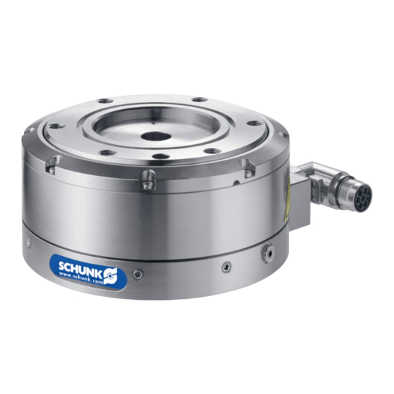
- Page 1 Electrical Rotary Module SCHUNK Torque Motor ERS 135-210 048V Assembly and Operating Manual 01.02/ERS 135-210 048V/en...
- Page 2 Imprint: Copyright: This manual remains the copyrighted property of SCHUNK GmbH & Co. KG. It is solely supplied to our customers and operators of our products and forms part of the unit. This documentation may not be duplicated or made accessible to third parties, in particular competitive companies, without our prior permission.
-
Page 3: Table Of Contents
Scope of delivery ..................15 Accessories ....................16 Technical Data ....................17 Basiscal data ........................17 6.1.1 Technical Data ERS 135 048V ..............17 6.1.2 Technical Data ERS 170 048V ..............20 6.1.3 Data ERS 210 048V ..................23 01.02/ERS 135-210 048V/en... - Page 4 Assembly ..................... 33 Mechanical connection ....................33 Electrical connection ....................... 36 Connection and operating with SCHUNK controller MCS 12 ......38 Scope of delivery of MCS 12 ..................40 Technical Data of the MCS 12 controller ..............41 Design and description of MCS 12 ................43 Assignment of the terminal strips of the MCS 12 ............
- Page 5 10.2.6 Commissioning of the digital outputs ............. 66 10.3 Control parameters ......................66 10.3.1 ERS 135 048V (Example for rotary module) ..........66 10.3.2 ERS 170 048V (Example for rotary module) ..........67 10.3.3 ERS 210 048V (Example for rotary module) ..........67 Replacing the controller ................
- Page 6 - MCDemo-Software * - EEPROM-Files for SCHUNK controller MCS 12 * - Function module FB10 for Siemens S7-300/400 for commissioning of SCHUNK-modules* Generall terms of business * The above with * characterized specified data can alternative be downloaded on the following page: * www.schunk.com...
-
Page 7: About This Manual
About this manual About this manual Purpose/validity This manual is part of the module and describes the safe and proper use during all phases of operation. This manual is valid only for the module specified on the front page. Target groups Target group Task Manufacturer, operator... -
Page 8: Symbols In This Manual
About this manual Symbols in this manual To give you quick access to information, the following symbols will be used in this guide: Symbol Meaning Dangers for persons. DANGER Nonobservance causes death or serious injuries. Dangers for persons. WARNNING Nonobservance can cause death or serious injuries. Warning of hot surfaces WARNING Information on avoiding material damage. -
Page 9: Basic Safety Notes
Basic safety notes Basic safety notes Intended use The ERS was designed to rotate loads, workpieces and objects. The ERS may only be operated in combination with a controller. The module is intended for installation in a machine. The requirements of the applicable guidelines must be observed and complied with. -
Page 10: Controlled Production
2.3.2 Constructional changes, attachments, or modifications Additional drill holes, threads, or attachments that are not offered as accessories by SCHUNK may be attached only with permission of SCHUNK. Non-authorized modifications results in the exclusion from product liability. -
Page 11: Obligations Of The Manufacturer/Operator
Basic safety notes Obligations of the manufacturer/operator 2.4.1 Choice of personnel and personnel qualifications Work on the module may be carried out by authorized personnel only. The legal minimum age must be observed. The assembly, commissioning and repair of the module may be performed only by trained specialist personnel who have been instructed how to perform the said work activities. -
Page 12: Personnel Qualification
Basic safety notes Personnel qualification 2.5.1 Safety-conscious working Avoid any manner of working that may interfere with the function and operational safety of the module. Observe the safety and accident-prevention regulations valid at the usage site. Wear protective equipment. 2.5.2 Safety measures during transport ... -
Page 13: Notes On Particular Risks
Basic safety notes Notes on particular risks Risk of injury from objects falling and being ejected! Provide protective equipment to prevent objects from falling or being ejected, such as processed workpieces, tools, chips, fragments, rejects. Adapt the operating conditions, e.g. reduce the velocity. Risk of injury when the machine/system moves unexpectedly! ... - Page 14 Basic safety notes WARNING Risk of burns due to contact with hot surfaces! During operation, the surface temperature of the ERS may exceed 85°C (185°F). Allow the module to cool down to at least 40°C (104°F) before working on the module. ...
-
Page 15: Warranty
Assembly and Operating Manual incl. a translation of the EC declaration of conformity in accordance with the low voltage directive SCHUNK CD with EEPROM-Files for SCHUNK controller MCS 12 and MCDemo-Software Function module FB10 for Siemens S7-300/400 for commissioning of SCHUNK-modules 01.02/ERS 135-210 048V/en... -
Page 16: Accessories
The following accessories are required for the module: Cable set (powercable/encoder cable) Y-junction ID-Nr. 9957232 Sensor cable ID-Nr. 9957233 The following accessories are available for the module: Controller: MCS 12 Order accessories separately. For additional accessories, see catalog or www.schunk.com. 01.02/ERS 135-210 048V/en... -
Page 17: Technical Data
Technical Data Technical Data Basiscal data Further technical data can be found in the SCHUNK catalog. The most recent version applies. 6.1.1 Technical Data ERS 135 048V Note All the technical data shown in the chart refer to the indicated heat conducting surface. - Page 18 [V] 5 ± 10 % mean current input [mA] pulse number per revolution [pulses/rev.] 22400 (on quadruple evaluation) resolution of the sensor [°] 0,016 Table 4 Technical Data ERS 135 048V 01.02/ERS 135-210 048V/en...
- Page 19 Figure 1 Swing time diagramm ERS 135 048V Parameter Description Swing time [s] Pulse off time [s] Table 5 Legend to Swing time diagramm ERS 135 048V Moment characteristics Figure 2 Moment characteristic ERS 135 048V 01.02/ERS 135-210 048V/en...
-
Page 20: Technical Data Ers 170 048V
Technical Data 6.1.2 Technical Data ERS 170 048V Note All the technical data shown in the chart refer to the indicated heat conducting surface. Type ERS 170 048V Mechanical operating data heat conducting surface [mm²] 49302 deadweight [kg] dimension (Ø x L) [mm] 170 x 66 center bore (Ø) [mm] ambient temperature [°C (°F)]... - Page 21 Technical Data Type ERS 170 048V temperature sensor (type) KTY84-130 max. permissible operating temperature +95 (+203) [°C (°F)] insulation class class F DIN 57530 output shaft power Pn [kw] 0,14 intermediate circuit voltage UZK [V] rated torque Mn [Nm] rated current In [A] 5,61 peak current Imax [A] 19,1...
- Page 22 Technical Data Swing time diagramm Figure 3 Swing time diagramm ERS 170 048V Parameter Description Swing time [s] Pulse off time [s] Table 7 Legend to Swing time diagramm ERS 170 048V Moment characteristic Figure 4 Moment characteristic ERS 170 048V 01.02/ERS 135-210 048V/en...
-
Page 23: Data Ers 210 048V
Technical Data 6.1.3 Data ERS 210 048V Note All the technical data shown in the chart refer to the indicated heat conducting surface. Type ERS 210 048V Mechanical operating data heat conducting surface [mm²] 37363 deadweight [kg] dimension (Ø x L) [mm] 210 x 77 center bore (Ø) [mm] ambient temperature [°C (°F)]... - Page 24 Technical Data ERS 210 048V Type temperature sensor (type) KTY84-130 max. permissible operating temperature +95 (+203) [°C (°F)] insulation class class F DIN 57530 output shaft power Pn [kw] 0,16 intermediate circuit voltage UZK [V] rated torque Mn [Nm] rated current In [A] 6,22 peak current Imax [A] torque constant K [Nm/A]...
- Page 25 Technical Data Swing time diagram Figure 5 Swing time diagram ERS 210 048V Parameter Description Swing time [s] Pulse off time [s] Table 9 Legend to Swing time diagram ERS 210 048V Moment characteristics Figure 6 Moment characteristics ERS 210 048V 01.02/ERS 135-210 048V/en...
-
Page 26: Requirements For The Power And Sensor Cables
Technical Data Requirements for the power and sensor cables Cable type power sensor number of wires 4x1mm² + 2x0,25mm² 4x2x0,25mm² min. cross-section of the wires [mm²] 0,25 max. cable diameter [mm] max. voltage [V] shielded twisted cable track compatible temperature application range [°C(°F)] +5 bis +55 +5 bis +55 (+41 to +131) -
Page 27: Technical Data For Brake Valve Mv15
Technical Data Figure 7 Brake design Pos. Description Contact surface between brake pad and rotor Pre-loaded brake piston with brake pad Table 11 Legend to Brake design 6.3.1 Technical data for brake valve MV15 Figure 8 Valve assembly Reference value Values Filtered compressed air, oiled or dry Permissible medium... -
Page 28: Connection To The Mcs 12 Controller
Technical Data The additional technical data presented in the data sheet for valve MV15 must also be observed. Applicable documents Note If there is a low level signal from the controller pending on the valve, the electropneumatic brake valve is closed. In this state, the brake is active. -
Page 29: Description Of The Module
Description of the module Description of the module ERS torque motor 7.1.1 Design and description of the ERS Figure 9 Components ERS Pos. Description Basic carrier (fixed) Rotor (moving) Bearing flange Sealing flange Plug connection Plug (sensor cable) Plug (power cable) Table 16 Legend to Components ERS Overview The ERS is a completely mounted, permanently excited synchronous... -
Page 30: Mechanical Interfaces
Description of the module Area of application The ERS is used typically for rotating and pivoting of large masses. The center bore can be used as a media feed-through. Operating modes The ERS must be operated using a controller. The following operating modes can be set: Torque-controlled Speed-controlled... -
Page 31: Elektrische Schnittstellen
Description of the module 7.1.3 Elektrische Schnittstellen Controller UVW + PE + Temp. Encoder Supply Encoder voltage Encoder system Encoder system ERS plug connection ERS basic carrier Winding Temperature sensor KTY84 Figure 10 ERS schematic diagram An incremental encoder (TTL signals) is installed as position feedback unit. -
Page 32: Type Key And Nameplate
I = incremental A = absolute The nameplate is mounted on the width side of the module. Designation Specifications manufacturer Schunk GmbH & Co. KG type / model – protection ERS210-048-40-B-N-I class 0310xxx rated torque (MN) 10 Nm... -
Page 33: Assembly
Assembly Assembly Mechanical connection WARNING Risk of injury when the machine/system moves unexpectedly! Switch off power supply. NOTICE Malfunctions due to mechanical stress in the housing possible Observe the requirements for the evenness of the mounting surface. Check the The values relate to the entire bolting surface. - Page 34 Assembly Align the zero point markings of the rotor and the base body so that they are at right angles on top of each other. Select the position of the ERS in the machine so that the zero pulse is in the middle of the moving range.
- Page 35 Assembly Note All dimensions of the drawings can be taken from our internet site under "CAD data service". Figure 12 View of the assembly of the adapter plates on rotor and basic Item Description Fastening screws M10 Centering pin D10/H7 Centering pin D5/H7 Fastening screws M12 Table 20 Legend to View of the assembly of the adapter plates on rotor and basic...
-
Page 36: Electrical Connection
Assembly Electrical connection DANGER Risk of fatal injuries due to electric shock! Switch off power supply. Disconnect the controller from the power supply. The intermediate circuit capacitors must be discharged. Observe the sequence when connecting the cables (grounding cable first, then conductors). - Page 37 4 Scope of delivery, page 15 The ERS must be connected to a controller. The cable colors and designations in the following tables apply to the SCHUNK connection cable. Observe the cable assignment. Function Signal Cable designation...
-
Page 38: Connection And Operating With Schunk Controller Mcs 12
Connection and operating with SCHUNK controller MCS 12 Connection and operating with SCHUNK controller MCS 12 NOTICE Malfunction in the event of an overload! Avoid impact loads. Do not exceed the bearing load limits NOTICE Malfunction in the event of overheating! ... - Page 39 Connection and operating with SCHUNK controller MCS 12 Starting up Connection the electrical connections (power cable, signal the ERS with any cable, Y-cable) to the controller. controller Check that the rotor can be turned freely. In doing so, pay attention to any grinding noise.
-
Page 40: Scope Of Delivery Of Mcs 12
Connection and operating with SCHUNK controller MCS 12 This stepping mode is used for incremental measuring systems after each restart of the controller. Scope of delivery of MCS 12 The MCS 12 is an accessory for the module and needs to be ordered separately. -
Page 41: Technical Data Of The Mcs 12 Controller
Connection and operating with SCHUNK controller MCS 12 Technical Data of the MCS 12 controller Technical Data MCS 12 motor/module/system ERS (48V) version ERS 135 ERS 170 ERS 210 0307035 0307036 0307037 General Technical Date IP rating IP30 power supply (logic) [V DC] power supply (load) [V DC] rated-/max. - Page 42 Connection and operating with SCHUNK controller MCS 12 Technical Data MCS 12 Control types/funktionalities PI-Current regulation, PI-Speed regulation P-Position regulation torque regulation yes, via current value Pseudo absolute-encoder-function, free programmable traversing blocks are technologic functions storable, controlled directly or traversing...
-
Page 43: Design And Description Of Mcs 12
Connection and operating with SCHUNK controller MCS 12 Design and description of MCS 12 Figure 13 Design of the MCS 12 controller Item Description Function Display LED red for ERR indicates an error Display LED green for RDY indicattes ready for communication... - Page 44 Connection and operating with SCHUNK controller MCS 12 Item Description Function terminal strip X2 digital inputs and outputs connection Profibus DP connection CAN Table 24 Figure 14 Dimension and mounting the MCS 12 controller Item Description Metal base bar for the mounting rail according to EN 50022.
- Page 45 Table 26 Anforderung an die Spannungsversorgung MCS 12 * e.g. with Siemens Sitop Modular (order No. at Siemens: 6EP1457-3BA00) DEFAULT function The module is reset to the factory setting using the SCHUNK controller. Notes Further information on the "DEFAULT values" can be found in the document MotionControl.pdf on the included cD of the controller.
-
Page 46: Assignment Of The Terminal Strips Of The Mcs 12
Connection and operating with SCHUNK controller MCS 12 Assignment of the terminal strips of the MCS 12 9.4.1 Assignment of terminal strip X1 Figure 15 Position of X1 terminal strip (motor and power supply for controller) Terminal Designation Type Cable color Meaning ERS 130–210... -
Page 47: Assignement Of Terminal Strip X2
+24V customer-specific Logic power supply (*) Wire color of the supplied SCHUNK cable, otherwise according to customer specifications Table 28 Pin-assignment of terminal X2 Position of terminal X2 Figure 13 Design of the MCS 12 controller, page 43 ... -
Page 48: Rs232 Connection
Connection and operating with SCHUNK controller MCS 12 9.4.4 RS232 connection Figure 16 Connector assignment for RS232 connection to MCS 12 Item Description Control system (PC / SPS) Soldering side of the 9-pin connector Figure of the 9-pin port of the MCS 12 controller Table 30 Connector assignment for RS232 connection to MCS 12 9.4.5... -
Page 49: Profibus Dp Connection
Connection and operating with SCHUNK controller MCS 12 9.4.6 Profibus DP connection Figure 18 Connector assignment for Profibus DP connection to MCS 12 Item Description Control system (PC / SPS) Soldering side of the 9-pin connector Figure of the 9-pin port of the MCS 12 controller Table 32 Connector assignment for Profibus DP connection to MCS 12 01.02/ERS 135-210 048V/en... -
Page 50: Connection Of The Interfaces Of The Mcs 12
Connection and operating with SCHUNK controller MCS 12 Connection of the interfaces of the MCS 12 9.5.1 Assignment of terminal X1 Terminal strip X1 is for connecting the motor phases and the power supply of the controller's power component. Table 27 Pin-assignment of terminal X1, page 46 ... -
Page 51: Electrical Connection Of The Module To The Mcs 12 Controller
Connection and operating with SCHUNK controller MCS 12 Electrical connection of the module to the MCS 12 controller DANGER Risk of fatal injuries due to electric shock! Switch off power supply. Disconnect the controller from the power supply. The intermediate circuit capacitors must be discharged. -
Page 52: Connecting The Rotary Module Ers 048V
Connection and operating with SCHUNK controller MCS 12 9.6.1 Connecting the Rotary Module ERS 048V Note It is recommended to implement the power supply for the logic via an external power supply source. Equipotential bonding is to be performed between the power supply sources for logic and output. -
Page 53: Communication Interfaces
Connection and operating with SCHUNK controller MCS 12 9.6.2 Communication interfaces The MCS 12 currently has three communication interfaces: RS232 Profibus DP The controller can be controlled via these interfaces using the SCHUNK Motion Protocol (SMP). All communication interfaces may be connected simultaneously. -
Page 54: Start-Up With Pc
Start-up with PC Start-up with PC 10.1 Functional priciple MCS 12 Power supply for controller Energy Motor phase Logic power supply supply Actuator Position measuring system (ERS) Controller Communication (MCS 12) (CAN, Profibus DP, RS232) Control system (Master) Temperature sensor monitoring Figure 19 Functional principle (example) The actuator (in this case ERS) is controlled by the external controller (MCS 12). -
Page 55: System Integration
The number of modules connected depends on the bus used. A maximum of 255 IDs can be assigned. CD, document: MotionControl.pdf 10.2.2 SCHUNK motion protocol Figure 20 The data frame of the Motion protocol always includes the following elements:... -
Page 56: Most Important Commands
Start-up with PC D-Len (Data Length) specifies the number of subsequent items of user data including the command byte. The data frame consists of one byte, therefore a Motion protocol message can transfer a maximum of 255 data bytes. The D-Len byte is always followed by the command code, consisting of one byte. - Page 57 Start-up with PC Referencing Command Code: 0x92 Description: A referencing is executed. Parameters (Master Slave): None. Response (Slave Master): "OK" (0x4F4B) if successful. The module executes the command. Miscellaneous: Spontaneous response possible. D-Len Param Meaning M S 0x01 0x92 S ...
- Page 58 Start-up with PC Current move Command Code: 0xB3 Description: A current move is executed. Parameters (Master Slave): Current in configured unit system (must be specified). Response (Slave Master): "OK" (0x4F4B) if successful. The module executes the command. Miscellaneous: Spontaneous message is possible. D-Len Param Meaning...
- Page 59 Start-up with PC Stop module Command Code: 0x91 Description: The module is braked and stopped in the current position. Parameters (Master Slave): None. Response (Slave Master): "OK" (0x4F4B) if successful. Miscellaneous: Spontaneous message is possible. D-Len Param Meaning M ...
- Page 60 Start-up with PC Acknowledge error Command Code: 0x8B Description: Acknowledgement of an error message. Parameters (Master Slave): None. Response (Slave Master): "OK" (0x4F4B) Miscellaneous: When all errors have been successfully acknowledged, after sending "OK" (0x4F4B), an info message "INFO NO ERROR"...
-
Page 61: Configuration With Mcdemo
The supplied CD is inserted. 1. Copy MCDemo from the enclosed CD: Figure 21 Start the CD and click on "Software". Then click on "MC-Demo.zip". Note The software is available for download at www.schunk.com. Observe the version status! 01.02/ERS 135-210 048V/en... - Page 62 Start-up with PC 2. Save the file and unpack the file: Figure 22 3. Start MC Demo by double-clicking on: Figure 23 4. Configure the communication interface: (choice between RS232, CAN or Profibus) Figure 24 01.02/ERS 135-210 048V/en...
- Page 63 Start-up with PC Select "Settings" "Open communication…" Figure 25 Select RS232 5. Search for the module: Figure 26 Select "Module" "Search bus". Figure 27 01.02/ERS 135-210 048V/en...
- Page 64 Start-up with PC 6. Enter or change parameters: Figure 28 Control window of the module found Select the [Parameters] tab and adjust the parameters (see "Motion Control" document). 7. Perform a reference run: Figure 29 Select the [Reference] button. 01.02/ERS 135-210 048V/en...
-
Page 65: Commissioning Of The Digital Inputs
Click on the desired tab (Relative position, Position, Speed etc.) and enter the desired target values in the input window. Note A password is required to change the control, referencing and device parameters. It is ―Schunk―. CD, document: MotionControl.pdf Note Further information: ... -
Page 66: Commissioning Of The Digital Outputs
22,8 0,026 1,98 0,006 0,07 864,0 4142,0 22,8 0,026 1,98 0,006 Table 40 Example control parameters for ERS 135 048V Note The control parameters are pre-configured with the moment of inertia of the rotor (ERS 135: 0,0014kgm²). 01.02/ERS 135-210 048V/en... -
Page 67: Ers 170 048V (Example For Rotary Module)
Start-up with PC 10.3.2 ERS 170 048V (Example for rotary module) Moment v_max a_max Kp_position Kp_speed Tn_speed Kp_current Tn_current of inertia [°/s] [°/s²] 0,025 2334,0 30309,5 0,016 50,6 0,004 0,05 1650,0 15126,1 0,016 50,6 0,004 1170,0 7563,0 16,7 0,016 50,6 0,004 0,15 954,0... -
Page 68: Replacing The Controller
Replacing the controller Replacing the controller DANGER Risk of fatal injuries due to electric shock! Switch off power supply. Only have the electrical connection established by the corresponding specialist personnel. Disconnect the controller from the power supply. The intermediate circuit capacitors must be discharged (wait approx. - Page 69 Replacing the controller 7. Package the old controller (if necessary, with a fault log) and store it at a dry place. 8. Mount the new controller on the DIN rail. chapter 9.3 Design and description of MCS 12, page 43 9.
-
Page 70: Troubleshooting
Check shaft encoder and its connection. Shaft encoder defective If a defect is detected: ERS must be sent to SCHUNK with a repair order. Check the difference of the winding resistance values. Do not exceed the difference. -
Page 71: Ers Overspeed
If the ERS has a ground leak while the power cable is electrical defect disconnected: ERS must be sent to SCHUNK with a repair order. Check the electrical connections. Incorrect phase connections chapter 8.2 Electrical connection, page 36 ... -
Page 72: Ers Oscillates
8.1 Mechanical connection, page 33 Check the parameters and setting values. Configuration incorrect Operating manual for the controller Bearing defective due to overload ERS must be sent to SCHUNK with a repair order. Table 46 01.02/ERS 135-210 048V/en... -
Page 73: Error Message For The Winding Temperature
Check resistance between the controller and the temperature sensor in the ERS. If the resistance exceeds 630 Ohms at room temperature: ERS must be sent to SCHUNK with a repair order. Note: The MCS 12 does not evaluate the tempature sensor. Thermal motor overload ... -
Page 74: Error Message Of The Controller Mcs 12
Troubleshooting 12.2 Error message of the controller MCS 12 12.2.1 Software error messages The MCS 12 controller indicates the error via the flashing red LED. To determine the error cause, MCS 12 controller must be connected to the PC. Consult the operating manual, MotionControl.pdf, and rectify the error. -
Page 75: „Pow" Led (Grün) Leuchtet Nicht
Troubleshooting 12.2.4 „POW“ LED (grün) leuchtet nicht Possible cause Corrective action Prüfen der Leistungsspannungsversorgung am MCS 12. Es liegt keine Spannung an.. chapter 9.4 Assignment of the terminal strips of the MCS 12, page 46 Table 50 12.2.5 „RDY“... -
Page 76: Maintenance And Care
60° C, the lubricants will harden faster. Lubrication and maintenance works have to be carried out more often. Recommendation Maintenance and seal replacement is done by SCHUNK because the rotor must be aligned and assembled with an assembly device. Maintenance Type... -
Page 77: Modul Servicing
Check the evenness of the mounting running smoothly surfaces. chapter 8.1 Mechanical connection, page 33 Or bearings defective: Consult your SCHUNK contact and send the ERS to SCHUNK along with a repair order. Table 54 01.02/ERS 135-210 048V/en... -
Page 78: Dismantling The Module
Refit the safety devices provided, such as covers and safety switches. 13.3 Dismantling the module The module may only be dismantled by SCHUNK as otherwise the mechanism or internal electronics may be damaged. Non-compliance will invalidate the warranty. Transport, storage and disposal 14.1... -
Page 79: Packing
14.4 Disposal Observe the locally valid legal disposal regulations. Environmentally sound disposal via the corresponding recycling or workshop centers. SCHUNK GmbH & Co. KG accepts no liability for the consequences of incorrect disposal by the customer. 01.02/ERS 135-210 048V/en... -
Page 80: Drawing
Drawing Drawing 15.1 ERS 135 Figure 31 Dimensions of the Torquemotors ERS 135 01.02/ERS 135-210 048V/en... -
Page 81: Ers 170
Drawing 15.2 ERS 170 Figure 32 Dimensions of the Torquemotors ERS 170 01.02/ERS 135-210 048V/en... -
Page 82: Ers 210
Drawing 15.3 ERS 210 Figure 33 Dimensions of the Torquemotors ERS 210 01.02/ERS 135-210 048V/en... -
Page 83: Ec Declaration Of Incorporation
EC declaration of incorporation EC declaration of incorporation In terms of the EC Machinery Directive 2006/42/EC, annex II, Part B Manufacturer/ SCHUNK GmbH & Co. KG. distributor Spann- und Greiftechnik Bahnhofstr. 106 – 134 D-74348 Lauffen/Neckar We hereby declare that the following product:... - Page 84 01.02/ERS 135-210 048V/en...
Need help?
Do you have a question about the ERS 135 048V and is the answer not in the manual?
Questions and answers