
Related Manuals for SCHUNK STM 48V


Summary of Contents for SCHUNK STM 48V
- Page 1 Electrical Rotary Module SCHUNK Torque Motor Type STM 48V Assembly and Operating Manual 05 V01-A/STM-48V/en/2011-04-01/CW Document last updated: 2011-04-01...
- Page 2 05/STM-48V/en/2011-04-01/CW...
- Page 3 Translation of the original manual Dear Customer, Congratulations on choosing a SCHUNK product. By choosing SCHUNK, you have opted for the highest precision, top quality and best service. You are going to increase the process reliability of your production and achieve best machining results –...
-
Page 4: Table Of Contents
Table of contents Table of contents About this manual ....................8 Purpose/validity ..................8 Target groups ..................... 8 Applicable documents ................8 Symbols in this manual ................9 Terms used in this manual ................. 9 Basic safety notes ....................10 Intended use .................... - Page 5 Assembly ......................27 Mechanical connection ................27 Electrical connection ................30 Start-up ........................ 32 Accessories ......................34 Connection and commissioning of the STM with the SCHUNK controller MCS-12 ..................34 9.1.1 Scope of delivery of the MCS-12 controller ......... 34 9.1.2 Technical Data of the MCS-12 controller ........
- Page 6 11.1.1 Most important commands ............60 Replacing the module ..................64 Troubleshooting....................65 13.1 SCHUNK Torque Motor STM ..............65 13.1.1 STM is not turning ............... 65 13.1.2 STM overspeed ................66 13.1.3 STM oscillates ................66 13.1.4 Bearing noise................66 13.1.5 Error message for the winding temperature ........
- Page 7 About this manual Drawing ........................ 73 16.1 STM-135 ....................73 16.2 STM 170....................74 16.3 STM-210 ....................75 Translation of original EC declaration of incorporation ........76 Contact ........................ 78 05/STM-48V/en/2011-04-01/CW...
-
Page 8: About This Manual
About this manual About this manual Purpose/validity This manual is part of the module and describes the safe and proper use during all phases of operation. This manual is valid only for the module specified on the front page. Target groups Target group Task ... -
Page 9: Symbols In This Manual
About this manual Symbols in this manual To give you quick access to information, the following symbols will be used in this guide: Symbol Designation Dangers for persons. DANGER Nonobservance causes death or serious injuries. Dangers for persons. WARNING Nonobservance can cause death or serious injuries. Information on avoiding material damage, for explanation or to optimize the work NOTICE processes. -
Page 10: Basic Safety Notes
Basic safety notes Basic safety notes Intended use The STM was designed to rotate loads, workpieces and objects. The STM may only be operated in combination with a controller. The module is intended for installation in a machine. The re- quirements of the applicable guidelines must be observed and complied with. -
Page 11: Controlled Production
6-2:2005); German version EN 61000-6-2:2005 2.3.3 Constructional changes, attachments, or modifications Additional drill holes, threads, or attachments that are not offered as accessories by SCHUNK may be attached only with permis- sion of SCHUNK. Non-authorized modifications results in the exclusion from prod- uct liability. -
Page 12: After-Sales Service
Basic safety notes 2.3.4 After-sales service SCHUNK's after-sales service is available for technical informa- tion and questions concerning SCHUNK products. Call the contact. (see chapter 18, page 78) State the ID of the module. (see chapter 6.1, page 20) Obligations of the manufacturer/operator 2.4.1... -
Page 13: Personnel Qualification
Basic safety notes Personnel qualification 2.5.1 Safety-conscious working Avoid any manner of working that may interfere with the function and operational safety of the module. Observe the safety and accident-prevention regulations valid at the usage site. Wear protective equipment. 2.5.2 Safety measures during transport ... -
Page 14: Notes On Particular Risks
Basic safety notes Notes on particular risks Risk of injury from objects falling and being ejected! Provide protective equipment to prevent objects from falling or being ejected, such as processed workpieces, tools, chips, fragments, rejects. Adapt the operating conditions, e.g. reduce the cycle time. Risk of injury when the machine/system moves unexpectedly! ... - Page 15 Basic safety notes Risk of burns due to contact with hot surfaces! During operation, the surface temperature of the STM may ex- ceed +85°C (+185°F). Allow the module to cool down to at least +40°C (+104°F) before working on the module. ...
-
Page 16: Warranty
The following accessories are required for the module: • Connection cable in the version ordered: – length 5m, 10m, 15m or 20m The following accessories are available for the module: • MCS-12 Controller Order accessories separately. For additional accessories, see catalog or www.schunk.com. 05/STM-48V/en/2011-04-01/CW... -
Page 17: Description Of The Module
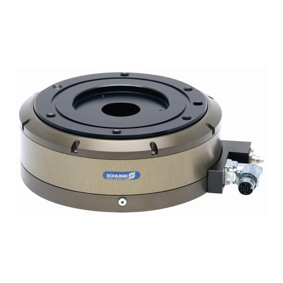
Description of the module Description of the module STM torque motor 5.1.1 Design and description of the STM 1 Basic carrier (fixed) 5 Plug connection 2 Rotor (moving) 6 Plug (sensor cable) 3 Bearing flange 7 Plug (power cable) 4 Sealing flange Figure 1 Components Overview... -
Page 18: Mechanical Interfaces
Description of the module 5.1.2 Mechanical interfaces Maintenance-free The STM is mounted on a single Franke bearing. This bearing is lubrication lubricated via one-time grease lubrication. Under normal operat- ing conditions lubrication for 20.000 operating hours is sufficient. The mechanical interfaces are shown on the drawing in chap- ter 16 page 73. -
Page 19: Type Key And Nameplate
40 = IP40 protection class The nameplate is attached to one of the broad sides of the mod- ule. Designation Specification manufacturer SCHUNK GmbH & Co. KG type / model - protection class STM210-48-S-N-40 03068xx rated torque (M 10 Nm... -
Page 20: Technical Data
Technical Data Technical Data Technical Data des STM Further technical data can be found in our catalog. The most re- cent version applies. 6.1.1 Technical Data STM135 Note All the technical data shown in the chart refer to the indicated heat conducting surface. -
Page 21: Technical Data Stm170
Technical Data Type STM135 48V temperature sensor (type) KTY84 max. permissible operating temperature [°C (°F)] +85 (+185) insulation class class F DIN 57530 output shaft power P [kw] 0,08 intermediate circuit voltage U rated torque M [Nm] rated current I 4,16 peak current I 12,98... - Page 22 Technical Data Type STM170 48V Max. +55 (+131) mass moment of inertia of rotating parts [kg m²] 0,003859 max. mass moment of inertia [kg m²] 0,14 rotation range [°] >360 (turning endlessly) positioning accuracy * [°] 0,02 Distribution of the end positions of 100 successive motions. When approaching from the same direction. measuring system Incremental IP rating...
-
Page 23: Technical Data Stm210
Technical Data Type STM170 48V mean current input [mA] pulse number per revolution [pulses/rev.] 25600 (on quadruple evaluation) absolute resolution of the sensor [°] 0,014 Table 7 6.1.3 Technical Data STM210 Note All the technical data shown in the chart refer to the indicated heat conducting surface. -
Page 24: Requirements For The Power And Sensor Cables
Technical Data Type STM210 48V max. permissible operating temperature [°C (°F)] +85 (+185) insulation class class F DIN 57530 output shaft power P [kw] 0,135 intermediate circuit voltage U rated torque M [Nm] rated current I 6,22 peak current I torque constant K [Nm/A] rated speed n [rpm]... -
Page 25: Brake
Technical Data Brake NOTICE This is not a service brake. Its use as a safety component is not permitted. The brake merely serves to support the standstill torque. Figure 3 Brake design Item Contact surface between brake pad and rotor Pre-loaded brake piston with brake pad Table 10 Legend of Figure 3 6.3.1... -
Page 26: Connection To Mcs-12
Technical Data The additional technical data presented in the data sheet for valve MV15 must also be observed. Note If there is a low level signal from the controller pending on the valve, the electropneumatic brake valve is closed. In this state, the brake is active. -
Page 27: Assembly
Assembly Assembly Mechanical connection WARNING Risk of injury when the machine/system moves unexpectedly! Switch off power supply. NOTICE Malfunctions due to mechanical stress in the housing possible Observe the requirements for the evenness of the mounting surface. Check the evenness of The values relate to the entire bolting surface. - Page 28 Assembly Align the zero point markings of the rotor and the base body so that they are at right angles on top of each other. Select the position of the STM in the machine so that the zero pulse is in the middle of the moving range.
- Page 29 Assembly Note All dimensions of the drawings can be taken from our internet site under "CAD data service". 1 - Fastening screws M10 3 - Centering pin D5/H7 2 - Centering pin D12/H7 4 - Fastening screws M12 Figure 6 View of the assembly of the adapter plates on rotor and basic carrier 05/STM-48V/en/2011-04-01/CW...
-
Page 30: Electrical Connection
Assembly Electrical connection DANGER Risk of fatal injuries due to electric shock! Switch off power supply. Disconnect the controller from the power supply. The intermediate circuit capacitors must be discharged. Observe the sequence when connecting the cables (grounding cable first, then conductors) ... - Page 31 The STM must be connected to a controller. The cable colors and designations in the following tables apply to the SCHUNK connection cable. Observe the cable assignment. Function Signal...
-
Page 32: Start-Up
Collisions in setup mode when the machine/system moves unexpectedly The motor could overspeed. Keep the motor's moving range (360°) free. Note The SCHUNK controller MCS-12 is recommended for the opti- mum use of the SCHUNK torque motor (STM). (see chapter 9 from page 34) 05/STM-48V/en/2011-04-01/CW... - Page 33 Start-up Connection the electrical connections (power cable, signal Starting up the STM with any cable) to the controller. controller Check that the rotor can be turned freely. In doing so, pay attention to any grinding noise. Check that all required contact protection measures were taken for moving and live parts.
-
Page 34: Accessories
Accessories Accessories Connection and commissioning of the STM with the SCHUNK controller MCS-12 9.1.1 Scope of delivery of the MCS-12 controller The MCS-12 is an accessory for the module and needs to be ordered separately. The scope of delivery includes: •... -
Page 35: Design And Description Of The Mcs-12 Controller
Accessories 9.1.3 Design and description of the MCS-12 controller Display LED green for RDY (indicates ready for communica- tion) Terminal strip X1 (motor and power sup- ply for controller) Display LED green Display LED red for POW for ERR (indicates availability (indicates an error) of power supply) Connection CAN... - Page 36 Accessories +48V +48V Figure 8 Position of X1 terminal strip (motor and power supply for controller) Figure 9 dimension and mounting the MCS-12 controller The MCS-12 controller is mounted by means of the metal base bar (90) on the mounting rail according to EN 50022. 05/STM-48V/en/2011-04-01/CW...
- Page 37 Accessories DEFAULT function The module is reset to the factory setting using the SCHUNK controller. Notes Further information on the "DEFAULT values" can be found in the document MotionControl.pdf on the included DVD of the controller. Perform the following steps: 1.
-
Page 38: Electrical Connection Of The Module To The Mcs-12 Controller
Accessories Electrical connection of the module to the MCS- 12 controller 9.2.1 Procedure and requirements DANGER Danger due to faulty connection Observe the pin assignment of the connecting terminals. Make sure that all components are grounded correctly. Requirements for Output power 48 V DC ±... -
Page 39: Assignment Of The Terminal Strips Of The Mcs-12 Controller
Customer-specific supply +24V Customer-specific Logic power supply (*)Wire color of the supplied SCHUNK cable, otherwise according to customer specifications Table 21: Pin assignment of terminal strip X2 – pins required to connect the encoder Terminal Designation Wire color (*) Meaning... -
Page 40: Communication Interfaces
+5 V white Power supply for encoder (*)Wire color of the supplied SCHUNK cable, otherwise according to customer specifications Table 22: Pin assignment of terminal strip X3 – pins required to connect the encoder 9.2.4 Communication interfaces The MCS-12 currently has three communication interfaces (RS232, CAN, Profibus DP). - Page 41 Accessories Figure 11 Connector assignment for CAN connection to MCS-12 Profibus DP The connection is established via a 9-pin Profibus connector from connection the control system (master) to the controller (MCS-12) (for the position of the connector, see Figure 7 page 35). Figure 12 Connector assignment for Profibus DP connection to MCS-12 Note Depending on the field bus system, up to 255 modules can be...
-
Page 42: Start Up With Pc
Start up with PC Start up with PC 10.1 SCHUNK MCS-12 controller 10.1.1 Functional principle Power supply for controller Energy Motor phases Logic power supply supply Controller Position measuring system (MCS-12) Communication (CAN, Profibus DP, RS232) Control system (Master) Temperature sensor monitoring... -
Page 43: System Integration
Module 3 (...) Figure 14 Data format The data is transferred in INTEL Format (Little Endian Format). SCHUNK motion Communication and data exchange with the module protocol Information for this see chapter 11 page 59 see MotionControl.pdf operating manual on the DVD for the MCS-12 controller. -
Page 44: Configuration With Mcdemo
1. Copy MCDemo from the enclosed DVD: Figure 15 Start the DVD and click on "Software". Then click on "MC-Demo.zip". Note The software is available for download at our website www.schunk.com. (see Service>Downloads>2.4 Mechatronics) Observe the version status! 05/STM-48V/en/2011-04-01/CW... - Page 45 Start up with PC 2. Save the file and unpack the file: Figure 16 3. Start MC Demo by double-clicking on: Figure 17 4. Configure the communication interface: (choice between RS232, CAN or Profibus) Figure 18 Select "Settings" "Open communication…". 05/STM-48V/en/2011-04-01/CW...
- Page 46 Start up with PC Figure 19 Select RS232 5. Search for the module: Figure 20 Select "Module" "Search bus". Figure 21 05/STM-48V/en/2011-04-01/CW...
- Page 47 Start up with PC 6. Enter or change parameters: Figure 22 Control window of the module found Select the [Parameters] tab and adjust the parameters (see "Motion Control" document). 7. Perform a reference run: Figure 23 Select the [Reference] button. 05/STM-48V/en/2011-04-01/CW...
-
Page 48: Commissioning Of The Digital Inputs
Click on the desired tab (Relative position, Position, Speed etc.) and enter the desired target values in the input window. Note A password is required to change the control, referencing and device parameters. It is “Schunk“. See Motion Control documentation. 10.2.3 Commissioning of the digital inputs ... -
Page 49: Control Parameters
Start up with PC 10.3 Control parameters 10.3.1 STM135 Mass moment of inertia KR_speed TN_speed KR_position 0,005 0,025 0,275 0,01 0,04 0,015 0,055 0,325 0,02 0,07 0,35 0,025 0,085 0,375 0,03 0,035 0,115 0,425 0,04 0,13 0,45 0,045 0,145 0,475 0,05 0,16 Table 23... - Page 50 Start up with PC STM 135 Readjustment time of the speed controller according to mass moment of inertia 0,18 0,16 0,14 Speed 0,12 controller 0,08 readjustment 0,06 time 0,04 0,02 0,005 0,015 0,025 0,035 0,045 0,055 Mass moment of inertia [kgm Figure 26 STM 135-48V Amplification of the position controller according to the...
- Page 51 Start up with PC STM 135 Speeds to be set according to the mass moment of inertia to be moved and the angle to be rotated 3.000 2.500 2.000 Speed 90° 1.500 [°/s] 180° 1.000 270° 360° 0,005 0,015 0,025 0,035 0,045 0,055...
-
Page 52: Stm170
Start up with PC 10.3.2 STM170 Mass moment of inertia KR_speed TN_speed KR_position 0,055 0,10 0,06 0,11 0,065 0,11 0,07 0,12 0,075 0,13 0,08 0,14 0,085 0,15 0,09 0,16 0,095 0,17 0,17 0,105 0,18 0,11 0,19 0,115 0,20 0,12 0,21 0,125 0,22 0,13... - Page 53 Start up with PC STM 170 - 48V Amplification of the speed controller according to the mass moment of inertia Speed amplifier KR 0,055 0,075 0,095 0,115 0,135 0,155 Mass moment of inertia [kgm Figure 30 05/STM-48V/en/2011-04-01/CW...
- Page 54 Start up with PC STM 170 - 48V Readjustment time of the speed controller according to the mass moment of inertia 0,30 0,25 0,20 Speed controller 0,15 TN readjustment time 0,10 0,05 0,00 0,055 0,075 0,095 0,115 0,135 0,155 Mass moment of inertia [kgm Figure 31 STM 170 - 48V Amplification of the position controller according to the...
- Page 55 Start up with PC STM 170 – 48V Speeds to be set according to the mass moment of inertia to be moved and the angle to be rotated Speed [°/s] Mass moment of inertia [kgm Figure 33 STM170 - 48V Acceleration values to be set for a maximum torque according to the mass moment of inertia to be moved 50.000...
-
Page 56: Stm210
Start up with PC 10.3.3 STM210 Mass moment of inertia KR_speed TN_speed KR_position 0,00 0,06 0,04 0,07 0,08 0,08 0,12 0,09 0,16 0,20 0,11 0,24 0,12 0,28 0,13 0,32 0,14 0,36 0,15 0,40 0,16 Table 25 STM 210 - 48V - 9860 STM 210 - 48V - 9860 Amplification of the speed controller according to the Verstärkung des Geschwindigkeitsreglers in Abhängigkeit vom... - Page 57 Start up with PC STM 210 - 48V Readjustment time of the speed controller according to the mass moment of inertia 0,18 0,16 0,14 Speed 0,12 controller readjustment 0,08 time 0,06 0,04 0,02 0,00 0,10 0,20 0,30 0,40 0,50 0,60 Mass moment of inertia [kgm²] Figure 36 STM 210 - 48V...
- Page 58 Start up with PC STM 210 - 48V - 9860 Speeds to be set according to the mass moment of inertia to be moved and the angle to be rotated 1.300 1.200 1.100 1.000 90° Speed [°/s] 180° 270° 360° Mass moment of inertia [kgm²] Figure 38 STM 210 - 48V...
-
Page 59: Schunk Motion Protocol
SCHUNK Motion protocol SCHUNK Motion protocol 11.1 Description Figure 40 The data frame of the Motion protocol always includes the follow- ing elements: • D-Len (1-byte) • Command Code (1 byte) D-Len (Data Length) specifies the number of subsequent items of user data including the command byte. -
Page 60: Most Important Commands
SCHUNK Motion protocol 11.1.1 Most important commands DANGER Risk of injury when the machine/system moves unexpectedly due to incorrect programming! Only specialist personnel or specially trained staff should carry out settings and enter parameters. Notes In all examples, only the necessary parameters are listed, not the optional parameters. - Page 61 SCHUNK Motion protocol Miscellaneous: Spontaneous response when position reached or in case of prior termination of positioning. D-Len Param Meaning M ► S 0x05 0xB0 0x00 0x00 0x20 0x41 Move to position 10.0[mm] S ► M 0x05 0xB0 0xCD 0xCC 0x04 0x41 Will reach position in 8.3[sec]...
- Page 62 SCHUNK Motion protocol Stop module Command Code: 0x91 Description: The module is braked and stopped in the current position. Parameters (Master ► Slave): None. Response (Slave ► Master): "OK" (0x4F4B) if successful. Miscellaneous: Spontaneous message is possible. D-Len Param Meaning M ►...
- Page 63 SCHUNK Motion protocol Miscellaneous: When all errors have been successfully ac- knowledged, after sending "OK" (0x4F4B), an info message "INFO NO ERROR" is also sent. D-Len Param Meaning M ► S 0x01 0x8B S ► M 0x03 0x8B 0x4F 0x4B...
-
Page 64: Replacing The Module
Replacing the module Replacing the module DANGER Risk of electric shock due to contact with live parts! Switch off the energy supply. Disconnect the MCS-12 controller from the power supply. Wait for approx. 5 minutes for the capacitors to discharge. WARNING Danger due to hot surfaces During normal operation, the module's surface may reach... -
Page 65: Troubleshooting
Short-circuit between turns in If the difference between the individual motor phases exceeds the motor 0.1 Ohm, the STM must be sent to SCHUNK with a repair order. Check the protective conductor. Short-circuit to ground due to Check the electrical connection and connectors for ground leakage. -
Page 66: Stm Overspeed
Check the evenness at the mounting surface (see Incorrect assembly chapter 7.1, page 27) Check the parameters and setting values (see Configuration incorrect operating manual for the controller). Send the module to SCHUNK with a repair order. Bearing defective due to overload Table 36 05/STM-48V/en/2011-04-01/CW... -
Page 67: Error Message For The Winding Temperature
Check the resistance of the temperature sensor. Temperature sensor defective If the resistance exceeds 630 Ohms at room temperature, the STM must be sent to SCHUNK with a repair order. Reduce the load. Thermal motor overload ... -
Page 68: Electrical Signals Are Not Transmitted
Troubleshooting 13.2.2 Electrical signals are not transmitted Possible cause Remedial measures Check the supply lines for defects Check the electrical connections Interruption in the supply lines (see chapter 9.2, page 38). Table 38 13.2.3 No LED lights up Possible cause Remedial measures ... -
Page 69: Maintenance And Care
60° C, the lubricants will harden faster. Lubrication and maintenance works have to be carried out more often. We recommend that maintenance and seal replacement is done by SCHUNK because the rotor must be aligned and assembled with an assembly device. Maintenance Type... -
Page 70: Dismantling The Module
Refit the safety devices provided, such as covers and safety switches. 14.3 Dismantling the module The module may only be dismantled by SCHUNK as otherwise the mechanism or internal electronics may be damaged. Non-compliance will invalidate the warranty. 05/STM-48V/en/2011-04-01/CW... -
Page 71: Transport, Storage And Disposal
Transport, storage and disposal Transport, storage and disposal 15.1 Transport • The packaging must protect the drive from all external effects (such as mechanical shocks and humidity). • Protect the module from shocks. • Package the module in such a way that the electrical supply lines do not obstruct transport and are not damaged themselves. -
Page 72: Storage
15.4 Disposal • Observe the locally valid legal disposal regulations. • Environmentally sound disposal via the corresponding recycling or workshop centers. • SCHUNK GmbH & Co. KG accepts no liability for the consequences of incorrect disposal by the customer. 05/STM-48V/en/2011-04-01/CW... -
Page 73: Drawing
Drawing Drawing 16.1 STM-135 Figure 41 Dimensions of the STM-135 torque motor 05/STM-48V/en/2011-04-01/CW... -
Page 74: Stm 170
Drawing 16.2 STM 170 Figure 42 Dimensions of the STM-170 torque motor 05/STM-48V/en/2011-04-01/CW... -
Page 75: Stm-210
Drawing 16.3 STM-210 Figure 43 Dimensions of the STM-210 torque motor 05/STM-48V/en/2011-04-01/CW... -
Page 76: Translation Of Original Ec Declaration Of Incorporation
Translation of original EC declaration of incorporation Translation of original EC declaration of incorporation In terms of the EC Machinery Directive 2006/42/EC, annex II B Manufacturer/ SCHUNK GmbH & Co. KG. distributor Spann- und Greiftechnik Bahnhofstr. 106 – 134 D-74348 Lauffen/Neckar, Germany... - Page 77 Translation of original EC declaration of incorporation 05/STM-48V/en/2011-04-01/CW...
-
Page 78: Contact
Contact Contact GERMANY – HEAD OFFICE CANADA DENMARK HUNGARY SCHUNK GmbH & Co. KG SCHUNK Intec Corp. SCHUNK Intec A/S SCHUNK Intec Kft. Spann- und Greiftechnik 190 Britannia Road East, Storhaven 7 Széchenyi út. 70. Bahnhofstrasse 106 – 134 Units 23-24... - Page 79 Contact JAPAN POLAND SOUTH KOREA SWITZERLAND, LIECHTEN- STEIN SCHUNK Intec K.K. SCHUNK Intec Sp.z o.o. SCHUNK Intec Korea Ltd. ul. Słoneczna 116 A 45-28 3-Chome Sanno # 907 Joongang SCHUNK Intec AG Ohta-Ku Tokyo 143-0023 Stara Iwiczna Induspia 2 Bldg., Im Ifang 12 Tel.
- Page 80 05/STM-48V/en/2011-04-01/CW...
Need help?
Do you have a question about the STM 48V and is the answer not in the manual?
Questions and answers