
Related Manuals for SCHUNK ERM Series


Summary of Contents for SCHUNK ERM Series
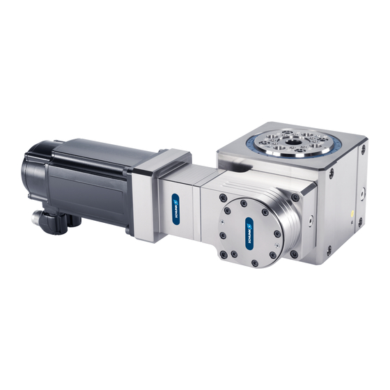
- Page 1 Translation of Original Operating Manual Assembly and Operating Manual Electric Rotary Module with Servo Motor...
- Page 2 Imprint Imprint Copyright: This manual is protected by copyright. The author is SCHUNK GmbH & Co. KG. All rights reserved. Technical changes: We reserve the right to make alterations for the purpose of technical improvement. Document number: 0389540 Version: 03.00 | 09/01/2023 | en...
-
Page 3: Table Of Contents
Table of Contents Table of Contents General........................ 5 About this manual.................... 5 1.1.1 Presentation of Warning Labels............... 5 1.1.2 Applicable documents ................ 6 1.1.3 Variants.................... 6 Warranty ...................... 7 Scope of delivery.................... 7 Accessories...................... 7 Basic safety notes .................... 8 Intended use ...................... 8 Not intended use .................... - Page 4 Table of Contents Troubleshooting ..................... 35 Module does not move? .................. 35 Does the module not provide the correct rotating angle? ........ 35 Torque drops...................... 35 Does module rotate jerkily or overshoot end position? ........ 36 Does module overshoot significantly at end positions? ........ 36 Is module turning too quickly / too slowly?............
-
Page 5: General
General 1 General 1.1 About this manual This manual contains important information for a safe and appropriate use of the product. This manual is an integral part of the product and must be kept accessible for the personnel at all times. Before starting work, the personnel must have read and understood this operating manual. -
Page 6: Applicable Documents
• Catalog data sheet of the purchased product * • Assembly and operating manuals of the accessories * The documents labeled with an asterisk (*) can be downloaded from schunk.com. 1.1.3 Variants This operating manual applies to the following variations: •... -
Page 7: Warranty
General 1.2 Warranty If the product is used as intended, the warranty is valid for 24 months from the ex-works delivery date under the following conditions: } 3 [ / 18] • Observe the maximum service life. • Observe the ambient conditions and operating } 2.4 [ / 8] conditions, •... -
Page 8: Basic Safety Notes
• Structural changes should only be made with the written approval of SCHUNK. 2.4 Environmental and operating conditions • Make sure that the product is a sufficient size for the application. -
Page 9: Personnel Qualification
Basic safety notes 2.5 Personnel qualification Inadequate qualifications of the personnel If the personnel working with the product is not sufficiently qualified, the result may be serious injuries and significant property damage. • All work may only be performed by qualified personnel. •... -
Page 10: Notes On Safe Operation
Basic safety notes 2.7 Notes on safe operation Incorrect handling of the personnel Incorrect handling and assembly may impair the product's safety and cause serious injuries and considerable material damage. • Avoid any manner of working that may interfere with the function and operational safety of the product. -
Page 11: Disposal
Basic safety notes 2.10 Disposal Handling of disposal The incorrect handling of disposal may impair the product's safety and cause serious injuries as well as considerable material and environmental harm. • Follow local regulations on dispatching product components for recycling or proper disposal. 2.11 Fundamental dangers General •... -
Page 12: Protection Against Dangerous Movements
Basic safety notes 2.11.3 Protection against dangerous movements Unexpected movements Residual energy in the system may cause serious injuries while working with the product. • Switch off the energy supply, ensure that no residual energy remains and secure against inadvertent reactivation. •... - Page 13 Basic safety notes • Check whether covers and protective devices are fitted to prevent contact with live components. • Do not touch the product's terminals when the power supply is switched on. Possible electrostatic energy Components or assembly groups may become electrostatically charged.
-
Page 14: Notes On Particular Risks
Basic safety notes 2.12 Notes on particular risks WARNING Risk of injury from objects falling and being ejected! Falling objects and objects being ejected can cause severe injuries. Ensure that the danger zone is enclosed by protective fencing • during operation. Mount the product onto the machine and the motor and the •... - Page 15 Basic safety notes WARNING Risk of injury due to sudden and unexpected movement of the machine/system! When the energy supply fails or the components malfunction, parts may move unexpectedly and cause severe injuries. Only expert personnel may operate. • Ensure that the danger zone (rotation of the add-on parts by a •...
- Page 16 Basic safety notes WARNING Risk of injury due to endless movement! Ensure that the danger zone is enclosed by protective fencing • during operation. Prevent destruction of attachments and their energy supply • (cables/hoses) using suitable guides/feed-throughs and movement limits. Check the position status (reference) of the motor sensor •...
- Page 17 Basic safety notes WARNING Risk of injury due to escaping hydraulic oil! Carry out a regular visual inspection for leaks. • Replace defective seals immediately. • Never remove the loss prevention device on the transmission • housing. Do not open the locking screws. •...
-
Page 18: Technical Data
Technical Data 3 Technical Data 3.1 Type Key and Name Plate ERM 160 - CB - 090 -B Size Number of media feed-throughs Range of functions CB: with center bore Transmission attachment direction Motor version B: Basic version without motor MSK050B: with motor MSK050B-0300-NN-M1-UG1-NNNN Gear ratio M max, in Maximum input... - Page 19 Technical Data Variant ERM160-MDF-090-B ERM160-MDF-090- MSK050B Gear mass moment of inertia (relative to drive) 0.000063 0.000063 [kgm²] Max. permissible axial force Fz [N] 3000 3000 Max. permissible radial force Fx [N] 1500 1500 Max. permissible moment load capacity My [Nm] Ambient temperature [°C] Min.
-
Page 20: Design And Description
Design and Description 4 Design and Description Main module Output flange (flange shaft) with compressed air connections for rotary feed- through Transmission housing (twistable) Drive shaft Distributor flange for rotary feed-through with center bore (compressed air connections on bottom) The torque of the motor is transferred from the driving shaft via the two-stage hypoid gearing to the output flange. -
Page 21: Transport And Storage
Transport and storage 5 Transport and storage 5.1 Transport 1. The packaging must protect the drive from all external effects (such as mechanical shocks and humidity). 2. Protect the module from shocks! 3. Remove the electrical feed lines before transportation. 4. -
Page 22: Assembly
Assembly 6 Assembly 6.1 Twist transmission housing WARNING Risk of injury due to escaping hydraulic oil! Never remove the loss prevention device (6) on the • transmission housing. Do not open the locking screws. • WARNING Risk of injury due to sudden and unexpected movement of the machine/system! Twisting of the transmission must be carried out before •... - Page 23 Assembly 1. Secure the rotary module on the base in such a way that the transmission (2) is on top. The mounting may only engage on the housing (1), but the ✓ drive shaft and output flange must move freely. 2.
-
Page 24: Mount Servo Motors
Assembly 6.2 Mount servo motors WARNING Risk of injury due to unexpected movements of the machine/ automated system! Before beginning any work on the machine and peripheral • equipment, disconnect them from the power supply (load and logic voltage) and secure against re-activation. Wait until the frequency converter/controller is discharged. - Page 25 Assembly ID number Designation Dimension X Dimension Y 0310572 MAS-ERM 8.0 -0.3 23.0 -0.3 160-19-080-100-M06 0310573 MAS-ERM 5.5 -0.3 22.0 -0.3 160-19-095-115-M08 1. Fit the coupling half (3) on the rotary module shaft (1) and adjust the dimension "X" in line with the table. 2.
-
Page 26: Mount Rotary Module Onto A Machine/System
Assembly 6.3 Mount rotary module onto a machine/system WARNING Risk of injury due to unexpected movements of the machine/ automated system! Before conducting any work on the machine and peripheral • equipment, disconnect them from the power supply (load and logic voltage) and secure against re-activation. - Page 27 Assembly The screws (1) and (2) are not included in the scope of ■ delivery. The centering sleeves Ø14 (3) are included in the accessory ■ pack. 1. Make sure that the flatness of the screw surface on the gantry complies with the requirements, see previous table.
- Page 28 Assembly Item Description Included in scope Not included in of delivery scope of delivery Centering sleeves Ø16 O-rings Cylindrical pin Screws 1. Grease O-rings (2) and press them into the counterbores. 2. If provided, fit cylindrical pin (3) (for the index bore hole) on the attachments.
-
Page 29: Electrical Connection
Assembly The channels for connection 1 and connection 8 are on the outside, with channel 1 on the distributor flange side, and channel 8 on the output flange side. On output flange 1. Connect the media feed-through using a hose-free direct connection. -
Page 30: Start-Up
Start-up 7 Start-up WARNING Risk of injury due to sudden and unexpected movement of the machine/system! When the energy supply fails or the components malfunction, parts may move unexpectedly and cause severe injuries. Only expert personnel may carry out start-ups. •... -
Page 31: Adjusting The Movement And Control Parameters, And The Exact Limits In The Controller
Start-up 7.1 Adjusting the movement and control parameters, and the exact limits in the controller NOTICE Overloading of the rotary module components due to angular momentum during emergency stop with holding brake possible, due to excessive input torques or collision with machine components. - Page 32 The speed of rotation must be further limited if the load can become too high even at lower speeds due to centrifugal forces. • The SCHUNK sales team can provide support in calculating the movement parameters and exact limits. • Be sure that the exact limits for the motor torque and the...
- Page 33 Start-up Moment of Position Proportional Speed inertia controller speed readjustment J [kgm²] Kv factor amplification time 0.09 0.08 • We recommend selecting the acceleration and speed parameters in such a way that the torque or current limitation is not active, or only to a limited extent. Otherwise, the control quality can be impaired (vibrations, overshoot, etc.), even to the extent of critical faults in the control loop resulting in an emergency stop (with holding brake in some circumstances).
- Page 34 Start-up Recommended acceleration (moment of inertia up to 20kgm²) 03.00 | ERM | Assembly and Operating Manual | en | 0389540...
-
Page 35: Troubleshooting
Component jammed. Check idle torque without motor. If necessary, send the module to SCHUNK with a repair order. Make sure that no chips or contamination is getting into the bearings during maintenance of the radial shaft sealing rings. -
Page 36: Does Module Rotate Jerkily Or Overshoot End Position
Application has changed. Make sure that separate parameter sets are used for applications that differ significantly (particularly high moments of inertia). Tooth clearance Check the tooth clearance. Send the module to SCHUNK with a increased repair order. Make sure that the module has only been used } 3 [ / within its defined application parameters, 18]. -
Page 37: Maintenance
Only have expert personnel carry out all disassembly and • maintenance work described in this operating manual. Disassembly beyond the degree described here may only be carried out by SCHUNK Service, otherwise the warranty expires, Warranty. Item Designation Piston seals on the media feed-through... - Page 38 *) Note: SCHUNK recommends having the radial shaft sealing rings (11) and (12) on the flange shaft and the radial shaft sealing ring (13) on the drive replaced by SCHUNK Service if required. Replacing other seals fitted in the module is not normally necessary, and may only be carried out by SCHUNK Service.
- Page 39 During operation, the tooth clearance can increase over the life span as shown in the diagram. If necessary, SCHUNK Service can reset the tooth clearance. Tooth clearance Tooth clearance [°]...
-
Page 40: Disassemble Servo Motor And Motor Adapter
Maintenance 9.1 Disassemble servo motor and motor adapter WARNING Risk of injury due to unexpected movement of the machine/ system! Before conducting any work on the machine and peripheral • equipment, disconnect them from the power supply (load and logic voltage) and secure against re-activation. Wait until the frequency converter/controller is discharged. - Page 41 Maintenance 2. Remove the mounting screws (8) on the motor adapter. 3. Detach the motor (2) from the motor adapter (6). 4. Remove the mounting screws (7). 5. Detach the motor adapter (6) from the rotary module (1). 03.00 | ERM | Assembly and Operating Manual | en | 0389540...
-
Page 42: Replacing The Media Feed-Through Seals
Maintenance 9.2 Replacing the media feed-through seals WARNING Risk of injury due to unexpected movement of the machine/ system! Before starting any work on the machine and peripheral • equipment, disconnect them from the power supply (load and logic voltage) and secure against re-activation. Wait until the frequency converter/controller is discharged. - Page 43 Maintenance NOTE } 9 [ / A suitable assembly kit is available from SCHUNK 38]. Refer to the instructions for assembly of the seals using the device. 1. Unscrew the four screws (2). 2. Carefully press distributor flange (1) from the opposite output side and then gradually remove it.
-
Page 44: Mount Seals Of The Media Feed-Through With The Assembly Device Erm 160-Mdf
Maintenance 9.3 Mount seals of the media feed-through with the assembly device ERM 160-MDF 1. Slide the wiper ring (4) onto the assembly sleeve (3). 2. Fit the expanding mandrel (5) on the assembly sleeve (3). 3. Place the seal (10) on the expanding mandrel (5). 4. - Page 45 Maintenance 5. Slide the assembly sleeve (3) onto the distributor flange (1) until the end of the sleeve reaches the desired sealing groove. 6. Detach the seal (10) with wiper ring (4) from the assembly sleeve into the sealing groove. NOTE •...
- Page 46 Maintenance Expanding mandrel (6) Wiper ring (5) 03.00 | ERM | Assembly and Operating Manual | en | 0389540...
- Page 47 Maintenance Pressure sleeve (7), material PA 6 03.00 | ERM | Assembly and Operating Manual | en | 0389540...
-
Page 48: Oil Change
Maintenance 9.4 Oil Change CAUTION Risk of injury due to leaking hydraulic oil! Hydraulic oil may cause irritation if it comes into contact with the skin and eyes. If hydraulic oil leaks, this poses a danger of slipping. Avoid skin contact with hydraulic oil. •... - Page 49 Maintenance Oil to be used: Castrol Optigear PD150 The module has two separate oil chambers Before an oil change, check the module for visible leaks and, if ■ necessary, replace the radial shaft seals during the oil change, } 9.5 [ / 50].
-
Page 50: Replace Radial Shaft Sealing Rings
9.5 Replace radial shaft sealing rings If oil is leaking from the rotary module, the radial shaft sealing rings must be replaced immediately. We recommend contacting the SCHUNK Service and having the radial shaft sealing rings replaced. NOTICE Property damage due to improperly carried out work! If the radial shaft sealing rings are incorrectly replaced, components may become damaged. -
Page 51: Disposal
Disposal 10 Disposal CAUTION Risk of injury due to leaking hydraulic oil! Hydraulic oil may cause irritation if it comes into contact with the skin and eyes. If hydraulic oil leaks, this poses a danger of slipping. Avoid skin contact with hydraulic oil. •... - Page 52 Disposal 3. SCHUNK accepts no liability for the consequences of improper disposal by the customer. Main components: • Aluminum • Steel • Exterior parts chemically nickel plated • Hydraulic oils, lubricating greases, adhesives (observe safety data sheet) • Plastics Motor: •...
-
Page 53: Translation Of The Original Declaration Of Incorporation
Directive 2006/42/EG, Annex II, Part 1.B of the European Parliament and of the Council on machinery. Manufacturer/ SCHUNK GmbH & Co. KG Clamping and gripping technology Distributor Bahnhofstr. 106 - 134 D-74348 Lauffen/Neckar We hereby declare that on the date of the declaration the following partly completed machine complied with all basic safety and health regulations found in the directive 2006/42/EC of the European Parliament and of the Council on machinery. -
Page 54: Ukca Declaration Of Incorporation
UKCA declaration of incorporation 12 UKCA declaration of incorporation in accordance with the Supply of Machinery (Safety) Regulations 2008. Manufacturer/ SCHUNK Intec Limited Distributor Clamping and gripping technology 3 Drakes Mews, Crownhill MK8 0ER Milton Keynes We hereby declare that on the date of the declaration the following partly completed machine complied with all basic safety and health regulations found in the "Supply of Machinery (Safety) Regulations 2008". -
Page 55: Annex To Declaration Of Incorporation
Annex to declaration of Incorporation 13 Annex to declaration of Incorporation in accordance with 2006/42/EC, Appendix II, no. 1 B as well as in accordance with the Supply of Machinery (Safety) Regulations 2008. 1. Description of the basic safety and health protection requirements, as per 2006/42/EC, Annex I and per the Supply of Machinery (Safety) Regulations 2008, that apply to and are fulfilled for the scope of the incomplete machine: Product designation Electric Rotary Module with Servo Motor... - Page 56 Annex to declaration of Incorporation Protection against mechanical hazards 1.3.3 Risks due to falling or ejected objects 1.3.4 Risks due to surfaces, edges or angles 1.3.5 Risks related to combined machinery 1.3.6 Risks related to variations in operating conditions 1.3.7 Risks related to moving parts 1.3.8 Choice of protection against risks arising from moving parts...
- Page 57 Annex to declaration of Incorporation Maintenance 1.6.4 Operator intervention 1.6.5 Cleaning of internal parts Information 1.7.1 Information and warnings on the machinery 1.7.1.1 Information and information devices 1.7.1.2 Warning devices 1.7.2 Warning of residual risks 1.7.3 Marking of machinery 1.7.4 Instructions 1.7.4.1 General principles for the drafting of instructions...
- Page 60 Translation of Original Operating Manual SCHUNK GmbH & Co. KG Clamping and gripping technology Bahnhofstr. 106 - 134 D-74348 Lauffen/Neckar Tel. +49-7133-103-0 Fax +49-7133-103-2399 info@de.schunk.com schunk.com Folgen Sie uns I Follow us...
Need help?
Do you have a question about the ERM Series and is the answer not in the manual?
Questions and answers