Advertisement
Quick Links
Advertisement

Subscribe to Our Youtube Channel
Related Manuals for Sartorius 2405


Summary of Contents for Sartorius 2405
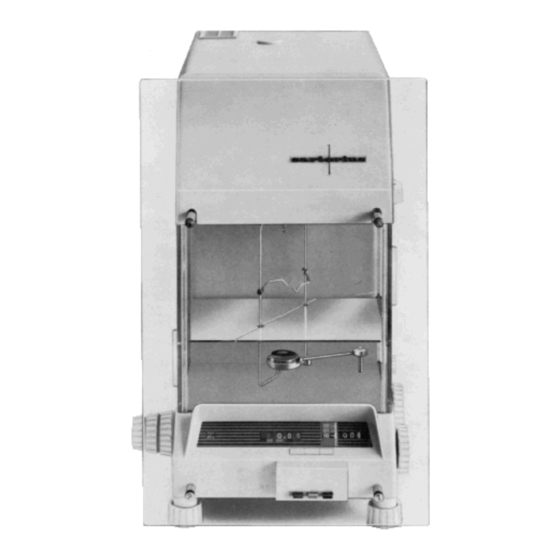
- Page 1 Digital Micro Balances 2405 Instructions for installation and operation...
- Page 2 UNPACKING INSTALLATION OF THE BALANCE 2.1. Checking the voltage setting 2.2. Detaching the transport arrestment 2.3. Assembling the balance 2.4. Inserting the glass plates 2.5. Leveling the balance DESCRIPTION OF THE OPERATING KNOBS CHECKING AND ADJUSTING 4.1. Focusing the projection scale 4.2.
-
Page 3: Installation
1. Unpacking 1.1. Carefully remove the balance from their cartons. 1.2. Carefully unpack accessories. 2. INSTALLATION 2.0.1. IMPORTANT: see supplement 6.1. to 6.4. 2.0.2. Remove outer and inner lid. 2.1. Checking the voltage setting: 2.1.1. Place balance on the rear on to the plastic dust cover. Push the cover plate in the base plate aside and change connecting wires, if necessary. - Page 4 2.2. Detaching the transport arrestment: 2.2.1. Weight application must indicate “29.99”. 2.2.2. Take off cover of the damping pot. 2.2.3. 3 Loosen knurled nuts, remove paper strips, swing aside springs and retighten nuts. Remove cardboard strip.
- Page 5 2.2.4. Take out balance beam. Take off 3 plastic discs (1). Loosen 3 knurled nuts (2), swing aside springs and retighten nuts. 2.2.5. Remove cardboard strip. Connect balance to the mains. Press gray push button (see 3.1.). 2.2.6. Remove brackets at the ends of the locking bars of the weight application. 2.2.7.
- Page 6 2.3. Assembling the balance: 2.3.1. Check arrestment pins (1), damping (2) and bearing (3) and clean, if necessary. 2.3.2. Check knife-edges and bearing and clean, if necessary. 2.3.3. Set balance beam on to the arrestment pins (1). The knife-edge must not come into contact with the bearing.
- Page 7 2.3.4. Place cover plate on to the damping pot and turn anti-clockwise until the slit the cover plate runs paral- lel with the balance beam. Turn clamp clockwise until it locks. 2.3.5. Check stirrup plate and clean, if necessary. Set stirrup plate on to the arrestment pins. 2.3.6.2.
- Page 8 2.3.7. Attach stirrup and insert it. 2.3.8. Unscrew 2 knurled nuts and take down carefully the locking plate for the weights. Put back the perfo- rated plate afterwards. 2.3.9. Attach lamp housing and plug in the cable. 2.3.10. Place the inside hood on to the balance.
- Page 9 2.3.11. Swing out pan lifting device. Open upper sliding door and attach pan bow. 2.4. Inserting the glass plates: 2.4.1. Place glass plate into the balance and close upper sliding door. Put the balance pan on to the holder and swing in the pan. 2.4.2.
- Page 10 2.4.3. Put locking screws for the front plate into position. 2.4.4. Fasten front plate. 2.4.5.Turn weight application to “0.00” and set micrometer to “00”.
- Page 11 2.5. Leveling the balance: Level balance by adjusting the front feet while observing the spirit level. 3. DESCRIPTION OF THE OPERATING KNOBS 3.1. Push buttons of the Auto-Arrest: 1: Balance arrested 2: Balance partly released. Switch weights are applied in this position 3: Balance fully released for the final weight indication.
- Page 12 3.2. Weight application: Knob c: Switch weights from 0.01 ..0.09 g Knob b: Switch weights from 0.1 ..0.9 g Knob a: Switch weights from 1 …..29 3.3. Knob for zero point adjustment. 3.4. Turning the knob clockwise: the lower sliding door is opened and the pan swings out. Turning the knob anti-clockwise: the balance pan swings in and the lower sliding door is closed.
- Page 13 3.5. The upper sliding door must be opened in order to place tubes and other large on to the hooks. 3.6. The left sliding door should not be opened unnecessarily. 3.7. Micrometer knob: After standstill of the projection scale turn micrometer knob until reading mark coincides with one line of the projection scale.
-
Page 14: Checking And Adjusting
4. CHECKING AND ADJUSTING 4.1. Focusing the projection scale: 4.1.1. Take off hood, release balance partly (press push button (2)) and adjust objective until projection scale is in focus. Arrest balance and place hood on the balance. 4.1.2. Brightness of the projection scale: release balance partly (press push button (2) ), loosen knurled screw and move lamp holder until Optimum brightness on the projection screen is achieved. - Page 15 4.2.2. If zero point acc. to 4.2.1. cannot be set, arrest balance and take off outer and inside hood. Direction of rotation at a - indication Direction of rotation at a + indication 4.3. Sensitivity: 4.3.1. Checking: Place a 10 mg weight on to the balance pan and turn weight application to "00.01". Release balance fully and set zero point.
- Page 16 4.3.3. Adjusting the sensitivity: pull plug out of the hood. if scale does not come up to “100” if scale swings beyond “100” 4.3.4. Repeat zero point and sensitivity adjustment alternately until both readings are correct. The balance must be checked again after approximately 1 hour. 5.
- Page 17 5.1.2. Release balance partly. Turn knob of the biggest weight decade until the projection scale swings into the minus range. Then turn knob on step back. 5.1.3. Proceed in the same way with the following smaller weight decades. Arrest balance and after a few seconds release the balance fully. After standstill of the projection scale turn the micrometer knob until reading mark coincides with one line of the projection scale.
- Page 18 5.2. Weighing procedure II: 5.2.1. Set zero point. Open upper sliding door, place sample on to the pan and dose sliding door. The weight is determined according to 5.1.2..5.1.4. 6. SUPPLEMENT 6.1. Accuracy of eight set lt is practically impossible to adjust all weights to a degree of perfection that errors can be eliminated completely.
- Page 19 6.3. The determination of atmospheric pressure and its influence on analytical weighings The demands in respect to the accuracy of analytical and especially of micro-analytical weighings are often extreme. Even though the accuracy required for the end result is usually only 1 %, the require- ment of a much higher accuracy is conditioned by the necessity of also having to weigh the mass of the tare which often exceeds to a considerable degree that of the proper sample.
- Page 20 The temperature in a laboratory may be 17°C in the morning and 21° in the afternoon when a weighing is repeated which was first made in the morning. lf one assumes that during the same time, the humid- ity fell from 50% to 40% and the barometer from 758 to 755, which variations are not uncommon, then using fig.
- Page 21 On the necessity of using corrections t is advisable to determine beforehand the approximate magnitude of the corrections which may have to be made. In the case of brass weights the buoyancy error is - 1,43) A ∙ 10 lf the deviations were less than 10 in which case the error would be no larger than 1 millionth of the sought result, then the buoyancy error remains below this value as long as the specific gravity is in ex- cess of 5 and the air buoyancy change remains below 1 %.
- Page 22 Fig. 3 shows the correction factors for glass ( = 2,5) in relation to the mass of the sample and the change in air buoyancy. = 2,5) Abb. 3. Buoyancy corrections for glass ( against brass weights = 8,4) in relation lo various changes of air buoyancy D.
- Page 23 Table 4 shows the relation for weighing in vacuum against the specific gravity of the sample. The cor- rection factor would be 3.5 mg if 10 grams of a sample of specific gravity 2.5 were weighed with brass weights. In reference to vacuum weighings one will have to take into special account the use of alumi- num fractional weights (usually up to 30 mg).
- Page 24 Under conditions of this kind the Sartorius balance ta- ble or console can be recommended.
-
Page 25: Environmental Effects
Fluorescent room lighting should be used, if at all feasible. Otherwise, a Sartorius balance lamp with cold light tube can be obtained. Even the body of the operator can influence the performance of a bal- ance, especially if it is used infrequently and if the doors are not opened repeatedly for the purpose of equalizing the inside and outside temperatures. -
Page 26: Technical Data
7. TECHNICAL DATA Digital Micro Balance 2405 Weighing range Built-in weight 0.01 — 29.99 Optical range 10 mg One scale division 0.1 mg Readability (micrometer) 0.001 mg Precision (standard deviation) 0.001 mg Literatur: Felgenträger, W.: Feine Waagen, Wägungen und Gewichte. Berlin 1932, S. 249-53 und Tabellen S. 297-302 U l brich t, H.: Die Berücksichtigung des Luftauftriebes bei analytischen Wägungen. - Page 28 All rights reserved. No part of this publication may be printed or translated in any form or by any means without the prior written permission of Sartorius AG. Sartorius AG reserves the right to make change to the technology, features, specification and design of the equipment without notice.
Need help?
Do you have a question about the 2405 and is the answer not in the manual?
Questions and answers