
Related Manuals for SeaLevel ACB-III


Summary of Contents for SeaLevel ACB-III
- Page 1 ACB-III User Manual | 4010 © Sealevel Systems, Inc. 4010 Manual | SL9151 11/2021...
-
Page 2: Table Of Contents
APPENDIX E – ASYNCHRONOUS AND SYNCHRONOUS COMMUNICATIONS ..................... 22 APPENDIX F – ACB DEVELOPER TOOLKIT AND ACB RESOURCE KIT ........................24 APPENDIX G – SILK SCREEN ......................................25 APPENDIX H – COMPLIANCE NOTICES ..................................26 WARRANTY ............................................27 © Sealevel Systems, Inc. 4010 Manual | SL9151 11/2021... -
Page 3: Introduction
Overview The Sealevel Systems ACB-III provides the PC with two high speed RS-232 synchronous / asynchronous ports. The ACB-III can be used in a variety of sophisticated communications applications such as SDLC, HDLC, X.25, Bi-Sync, and high speed async. © Sealevel Systems, Inc. -
Page 4: Before You Get Started
Before You Get Started What’s Included The ACB-III is shipped with the following items. If any of these items are missing or damaged, contact the supplier. • ACB-III Serial Interface Adapter • Channel B Interface Cable Advisory Conventions Warning The highest level of importance used to stress a condition where damage could result to the product, or the user could suffer serious injury. - Page 5 The ACB-III factory default settings are as follows: Base Address DMA Channels Channel A / B Half Duplex DMA To install the ACB-III using factory default settings, refer to the section on Installation. For your reference, record installed ACB-III settings below: Base Address DMA Channels ©...
-
Page 6: Card Setup
The ACB-III contains several jumper straps which must be set for proper operation. Address Selection The ACB-III occupies 8 consecutive I/O locations. A DIP-switch (SW2) is used to set the base address for these locations. The ACB-III can reside in any I/O location between 100 and 3F8 Hex. Be careful when selecting the base address as some selections conflict with existing PC ports. - Page 7 Where "Base" is the selected base address. IRQ Selection (Header E8) The ACB-III has an interrupt selection jumper which should be set prior to use if an interrupt is required by your application software. Consult the user manual for the application software being used to determine the proper setting.
- Page 8 Card Setup, Continued DMA Options Headers E4 and E5 select the Direct Memory Access (DMA) mode of operation for the ACB-III. Channel A of the SCC can operate in either half-duplex or full duplex DMA mode. Full duplex DMA can transmit and receive data simultaneously.
- Page 9 Both DMA Channels (1 and 3) Selected: Ch.A DMA Ch.1 Half Duplex 1,4,5 WAIT/REQ A Ch.B DMA Ch.3 Half Duplex WAIT/REQ B Ch.A DMA Ch.3 Half Duplex 2,3,5 WAIT/REQ A Ch.B DMA Ch.1 Half Duplex WAIT/REQ B © Sealevel Systems, Inc. 4010 Manual | SL9151 11/2021...
- Page 10 The TXC pin (15) can be jumpered as either an input or an output. The TSET pin (24) will always echo the TXC pins, regardless of whether the TXC pins are selected as an input or an output. © Sealevel Systems, Inc. 4010 Manual | SL9151 11/2021...
- Page 11 E2 & E10: 15 17 O I O I Transmit Clock Output (15) Transmit Clock Input (15) Receive Clock Input (17) Figure 9 - Header E2 and E10 (shown in factory default) © Sealevel Systems, Inc. 4010 Manual | SL9151 11/2021...
-
Page 12: Installation
Installation Hardware Installation The ACB-III can be installed in any of the PC expansion slots. The ACB-III contains several jumper straps for each port which must be set for proper operation. Do not install the Adapter in the machine until the software has been fully installed. - Page 13 The SeaMAC software for the ACB-III is available upon request. For additional software support, please call Sealevel Systems’ Technical Support, (864) 843-4343. Our technical support is free and available from 8:00AM-5:00PM Eastern Time, Monday through Friday. For email support contact: support@sealevel.com.
-
Page 14: Technical Description
Control/Status Port The ACB-III occupies eight Input/Output (I/O) addresses. The first four are used by the SCC chip, while the fifth address (Base+4) is the address of the on-board Control/Status Port. This port is used to set the Data Terminal Ready (DTR) signal, to enable or disable DMA under program control, and to monitor the Data Set Ready (DSR) input signals from the modem. - Page 15 85230 SCC recovery time specification. Please refer to the 85230 technical reference for more details. Correct: Incorrect: MOV DX,3E0H MOV DX,3E0H OUT DX,AL OUT DX,AL JMP $+2 OUT DX,AL OUT DX,AL © Sealevel Systems, Inc. 4010 Manual | SL9151 11/2021...
- Page 16 RTS to CTS and RI. Also, connect DCD to DTR and DSR. Terminating these pins, if not used, will help insure you get the best performance from your adapter. © Sealevel Systems, Inc. 4010 Manual | SL9151 11/2021...
-
Page 17: Specifications
Non-Condensing Non-Condensing Manufacturing All Sealevel Systems Printed Circuit boards are built to UL 94V0 rating and are 100% electrically tested. These printed circuit boards are solder mask over bare copper or solder mask over tin nickel. Power Consumption Supply line... -
Page 18: Appendix A - Troubleshooting
No two adapters can occupy the same I/O address. 3. Make sure the Sealevel Systems adapter is using a unique IRQ. The IRQ is typically selected via an on-board header block. Refer to the section on Card Setup for help in choosing an I/O address and IRQ. -
Page 19: Appendix B - How To Get Assistance
If possible, please have the adapter installed in a computer ready to run diagnostics. Sealevel Systems provides an FAQ section on its web site. Please refer to this to answer many common questions. This section can be found at http://www.sealevel.com/faq.asp. -
Page 20: Appendix C - Electrical Interface
0 (space) and -12 volts (-3 to -10 volts) denotes a binary 1 (mark). The RS-232 and the EIA/TIA-574 specification defines two type of interface circuits, Data Terminal Equipment (DTE) and Data Circuit-Terminating Equipment (DCE). The Sealevel Systems adapter is a DTE interface. © Sealevel Systems, Inc. -
Page 21: Appendix D - Direct Memory Access
I/O. In order to provide a means for higher rate data transfers, a special function called Direct Memory Access (DMA) was built into the original IBM PC. The DMA function allows the ACB-III (or any other DMA compatible interface) to read or write data to or from memory without using the Microprocessor. -
Page 22: Appendix E - Asynchronous And Synchronous Communications
The communication parameters are baud rate, parity, number of data bits per character, and stop bits (i.e., 9600, N,8,1). © Sealevel Systems, Inc. 4010 Manual | SL9151 11/2021... - Page 23 (either another sync flag or a bit combination that signals the end of the text, e.g., EOT). The actual sync flag and protocol varies depending on the sync format (SDLC, BISYNC, etc.). © Sealevel Systems, Inc. 4010 Manual | SL9151 11/2021...
-
Page 24: Appendix F - Acb Developer Toolkit And Acb Resource Kit
ACB family. The ACB Resource Kit provides a brief overview of the ACB product line. Both of these kits are available at your request. For additional information, please contact Sealevel Systems, Inc. Technical Support for assistance: Available Monday –... -
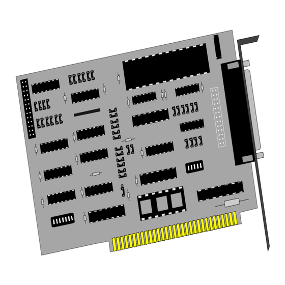
Page 25: Appendix G - Silk Screen
Appendix G – Silk Screen © Sealevel Systems, Inc. 4010 Manual | SL9151 11/2021... -
Page 26: Appendix H - Compliance Notices
Always use cabling provided with this product if possible. If no cable is provided or if an alternate cable is required, use high quality shielded cabling to maintain compliance with FCC/EMC directives. © Sealevel Systems, Inc. 8004 Manual | SL9022 9/2021... -
Page 27: Warranty
Sealevel's commitment to providing the best I/O solutions is reflected in the Lifetime Warranty that is standard on all Sealevel manufactured I/O products. We are able to offer this warranty due to our control of manufacturing quality and the historically high reliability of our products in the field. Sealevel products are designed and manufactured at its Liberty, South Carolina facility, allowing direct control over product development, production, burn-in and testing.
Need help?
Do you have a question about the ACB-III and is the answer not in the manual?
Questions and answers