Table of Contents
Advertisement
Quick Links
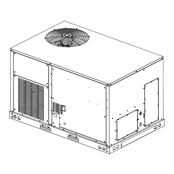
APG16 "M" SERIES with r-
Single Package Gas-Electric Heating & Cooling Unit
Installation Instructions
This forced air central unit design complies with
requirements embodied in The American National Standard
/ National Standard of Canada ANSI Z21.47•CSA-2.3 Gas-
fired central furnaces.
Our continuing commitment to quality products may mean a change in specifications without notice.
IOA-3017J
07/2021
410
19001 Kermier Rd., Waller, TX 77484
www.goodmanmfg.com
©2016-2021 Goodman Manufacturing Company, L.P.
i
s a registered trademark of Maytag Corporation or its related companies and is used under license. All rights reserved.
a
TABLE OF CONTENTS
Replacement Parts.........................................................2
Safety Instructions........................................................2
General information......................................................3
Clearances.............................................................5
Roof Curb Post-Installation checks..........................6
Roof Top Duct Connections..........................................6
Rigging Details.................................................................6
Weights and Center of Gravity....................................7
Electrical wiring............................................................7
Gas Supply Piping..........................................................9
Propane Gas Installations...........................................11
Circulating Air and Filters.........................................12
Condensate Drain Connection....................................12
Startup, Adjustments, and Checks............................13
Air flow Adjustments...................................................14
Gas System Check.........................................................14
Normal Sequence Of Operation.................................18
Maintenance...................................................................20
Troubleshooting..........................................................22
Appendix A Blower Performance Tables.................24
Appendix B Electrical Data........................................25
Appendix C Unit dimensions.........................................26
Appendix D Min-Max Airflow.......................................27
Wiring Diagram............................................................28
Startup Checklist..........................................................29
Only personnel that have been trained to install, adjust,
service or repair(hereinafter, "service") the equipment
specified in this manual should service the equipment.
The manufacturer will not be responsible for any injury
or property damage arising from improper service or
service procedures. If you service this unit, you assume
responsibility for any injury or property damage which may
result. In addition, in jurisdictions that require one or more
licenses to service the equipment specified in this manual,
only licensed personnel should service the equipment.
Improper installation, adjustment, servicing or repair of
the equipment specified in this manual, or attempting to
install, adjust, service or repair the equipment specified in
this manual without proper training may result in product
damage, property damage, personal injury or death.
• www.amana-hac.com
WARNING
Advertisement
Table of Contents

Related Manuals for Amana APG16 M Series


Summary of Contents for Amana APG16 M Series
-
Page 1: Table Of Contents
Our continuing commitment to quality products may mean a change in specifications without notice. 19001 Kermier Rd., Waller, TX 77484 www.goodmanmfg.com • www.amana-hac.com IOA-3017J ©2016-2021 Goodman Manufacturing Company, L.P. 07/2021 s a registered trademark of Maytag Corporation or its related companies and is used under license. All rights reserved. -
Page 2: Replacement Parts
REPLACEMENT PARTS WARNING Ordering Parts To prevent the risk of property damage, personal injury, or When reporting shortages or damages, or ordering repair death, do not store combustible materials or use gasoline parts, give the complete unit model and serial numbers as or other flammable liquids or vapors in the vicinity of this stamped on the unit’s nameplate. -
Page 3: General Information
Amana brand products. Within the ® This ven la on is necessary to avoid the danger of CO poisoning which... - Page 4 Obtain from: American National Standards Institute Pre-Installation Checks 25 West 43rd Street, 4th Floor Carefully read all instructions for the installation prior New York, NY 10036 to installing unit. Ensure each step or procedure is understood and any special considerations are taken into System design and installation should also, where account before starting installation.
- Page 5 • The unit shall not be connected to a chimney flue Unit Precautions serving a separate appliance designed to burn solid fuel. • Do not stand or walk on the unit. • To avoid possible illness or death of the building •...
-
Page 6: Clearances
NOTE: The unit and curb accessories are designed to allow vertical duct installation before unit placement. Duct installation after unit placement is not recommended. CAUTION All curbs look similar. To avoid incorrect curb positioning, check job plans carefully and verify markings on curb assembly. -
Page 7: Rigging Details
Remove wood struts mounted beneath unit base frame before setting unit on roof curb. These struts are intended to protect unit base frame from fork lift damage. Removal is accomplished by extracting the sheet metal retainers and pulling the struts through the base of the unit. -
Page 8: Electrical Wiring
For unit protection, use a fuse or HACR circuit breaker that Corner Weights (lb) Shipping Operating Model X (in) Y (in) is in excess of the circuit ampacity, but less than or equal Weight (lb) Weight (lb) to the maximum overcurrent protection device. DO NOT APG1660140M41 35.8 27.5 EXCEED THE MAXIMUM OVERCURRENT DEVICE SIZE... - Page 9 CSA C22.1, Part 1. A ground lug is provided for this Units installed on Roof Tops purpose. Do not use the ground lug for connecting a Main power and low voltage wiring may enter the unit neutral conductor. through the condenser end of unit or through the roof curb. •...
-
Page 10: Gas Supply Piping
4. Route thermostat wires from sub-base terminals INLET GAS PRESSURE to the unit. Control wiring should enter through the condenser panel opening or through curb indicated in NATURAL Min. 5.0" W.C., Max. 10.0" W.C. “Electrical Entrance” figure. Connect thermostat and PROPANE Min. -
Page 11: Propane Gas Installations
3. Use ground joint unions. Gas Piping Checks 4. Install a drip leg to trap dirt and moisture before it can CAUTION enter the gas valve. The drip leg must be a minimum of three inches long. To prevent property damage or personal injury due to fire, 5. - Page 12 For satisfactory operation, propane gas pressure must be 1. Route gas piping to unit so that it does not interfere within 9.7 - 10.3 inches w.c. for high fire at the manifold with the removal of access panels. Support and with all gas appliances in operation.
-
Page 13: Circulating Air And Filters
DRAIN WARNING CONNECTION This unit and its individual shutoff valve must be UNIT 2" MINIMUM DISCONNECTED from the gas supply system during any pressure testing of that system at test pressures in excess of ½ PSIG (13.8” w.c.). FLEXIBLE CAUTION TUBING-HOSE 3"... -
Page 14: Air Flow Adjustments
Prior to the beginning of Startup, Adjustments, and Checks • Requirements are met for venting and combustion air. procedures, the following steps should be completed in the • Air filters are in place. building. • Input rate and temperature rise are adjusted per rating plate. -
Page 15: Gas System Check
If an economizer is installed, check the unit operating 6. Move the gas control valve switch to the OFF position. balance with the economizer at full outside air and at 7. Wait five minutes to clear out any gas. minimum outside air. 8. - Page 16 gas 2.0” w.c., 6.0” w.c. low fire propane gas. Minimum gas With Power And Gas On: supply pressure is 5.0” w.c. for natural gas and 11.0” w.c. 2. Put unit into heating cycle and turn on all other gas for propane gas. consuming appliances.
- Page 17 Wiring Example...
- Page 18 To measure the gas input use a gas meter and proceed as To connect manometer to gas valve: follows: 1. Back outlet pressure tap screw (inside inlet pressure 1. Turn off gas supply to all other appliances except the boss) out one turn (counterclockwise, not more than unit.
-
Page 19: Normal Sequence Of Operation
With a properly designed system, the proper amount of will close the gas valve and lock itself out. It may be temperature rise will normally be obtained when the unit reset by momentarily interrupting power. This may be is operated at rated input with the recommended blower accomplished by briefly lowering the room thermostat speed. - Page 20 7. Turn the temperature setting to the highest position, stopping the unit. The indoor blower will continue to WARNING run for 60 seconds. 8. Turn the thermostat system switch to “OFF” and To avoid property damage, personal injury or death due to fire or explosion, a qualified servicer must investigate the disconnect all power when servicing the unit.
-
Page 21: Maintenance
9. Increasing the room cooling setpoint to a value above the current room temperature will simulate a satisfied WARNING thermostat. The compressor and the supply fan will cycle off. HIGH VOLTAGE! 10. After a time delay of approximately 3 minutes, the Disconnect all power before servicing or installing this unit. - Page 22 Filters NOTE: After cleaning, the microamp signal should be stable and in the range of 4 - 6 microamps DC. CAUTION Flue Passages (Qualified Servicer Only) To prevent property damage due to fire and loss of At the start of each heating season, inspect and, if equipment efficiency or equipment damage due to dust and necessary, clean the unit flue passage.
-
Page 23: Troubleshooting
Internal Control Failure If the integrated ignition control in this unit encounters an internal fault, it will go into a “hard” lockout and turn off the diagnostic LED. If diagnostic LED indicates an internal fault, check power supply to unit for proper voltage, check all fuses, circuit breakers and wiring. - Page 24 • Check rollout limit Open Thermal Protection Device (4 FLASH CODE) If the burner flames are not properly drawn into the heat If the primary limit switch opens, the gas valve is exchanger, the flame rollout protection device will open. immediately deenergized, the induced draft and air Possible causes are restricted or blocked flue passages, circulating blowers are energized.
-
Page 25: Appendix A Blower Performance Tables
APPENDIX A BLOWER PERFORMANCE TABLES 5 Ton Models: APG1660140M41 Standard Static Drive Burners High Fire Input: 140,000 BTU/HR Horizontal Flow Down Flow External External Speed Static Speed Static SCFM SCFM Pressure Pressure (ESP), in w.c. (ESP), in w.c. 0.14 1003 606 0.14 0.16 0.17... -
Page 26: Appendix B Electrical Data
APPENDIX B ELECTRICAL DATA Electrical Data Outdoor Fan Optional Electric Optional Powered Optional Electrical Compressor Indoor Fan Motor Power Supply Model Number Motor Heat Convienience Power Rating QTY RLA LRA QTY HP FLA Type HP FLA Part # KW* FLA Outlet FLA Exhaust FLA Direct... -
Page 27: Appendix C Unit Dimensions
APPENDIX C UNIT DIMENSIONS 47-5/8" 73-3/8" "A" 74" 48-5/16" Model size DIM “A” 5 ton 43-1/2” 19-1/2 RETURN 5-5/16 11” X 25” EMBOSS DRAIN 5-7/8 THRU THRU CURB BASE LOCATION SUPPLY UTILITIES 12” X 17” 7-3/8 27-3/4 RETURN 4-1/2 11" X 25" 7-1/2 7-5/8 SUPPLY... -
Page 28: Appendix D Min-Max Airflow
APPENDIX D MIN-MAX AIRFLOW AIR FLOW RANGE FOR HIGH STAGE HEATING COOLING HEAT HIGH FIRE RATE MAXIMUM UNIT MINIMUM MINIMUM RANGE BTU/HR SCFM SCFM SCFM APG1660140M41 HIGH 140,000 1615 1500 2500... -
Page 29: Wiring Diagram
WIRING DIAGRAM Wiring is subject to change. Always refer to the wiring diagram on the unit for the most up-to-date wiring. -
Page 30: Startup Checklist
START-UP CHECKLIST Residential Package - (Indoor Section) Model Number Serial Number ELECTRICAL Line Voltage (Measure L1 and L2 Voltage) L1 - L2 Secondary Voltage (Measure Transformer Output Voltage) R - C Blower Amps Heat Strip 1 - Amps Heat Strip 2 - Amps BLOWER EXTERNAL STATIC PRESSURE Return Air Static Pressure IN. - Page 31 THIS PAGE IS LEFT INTENTIONALLY BLANK.
- Page 32 Please fill out the feedback form on one of the following links: Goodman Brand Products: (http://www.goodmanmfg.com/about/contact-us). ® Amana Brand Products: (http://www.amana-hac.com/about-us/contact-us). ® You can also scan the QR code on the right for the product brand you purchased to be directed to the feedback page. GOODMAN BRAND ®...
Need help?
Do you have a question about the APG16 M Series and is the answer not in the manual?
Questions and answers