Advertisement
Quick Links
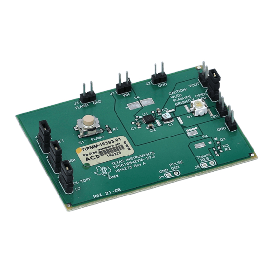
This user's guide describes the characteristics, operation, and use of the TPS61054EVM-273 evaluation
module
(EVM).
boost-converter-based high-power WLED driver. This document includes setup instructions, a schematic
diagram, a bill of materials, and PCB layout drawings for the evaluation module.
...................................................................................................................
1
Introduction
2
Input/Output Connector Descriptions
3
Test Results
4
Board Layout
5
Schematic and Bill of Materials
6
Related Documentation From Texas Instruments
1
LED Efficiency vs Input Voltage – Torch Mode with ILED=75mA
2
LED Efficiency vs Input Voltage – Single-Pulse Flash Mode with ILED=700mA
3
Torch Flash Sequence
4
Start-Up in Torch
5
Voltage-Mode Efficiency
6
Voltage-Mode Load Transient
7
Assembly Layer
.....................................................................................................................
8
Top Layer
........................................................................................................................
9
Layer 2
.......................................................................................................................
10
Layer 3
11
Bottom Layer
12
TPS61054/5EVM-273 Schematic
1
Typical Performance Specification Summary
2
Jumper Settings
3
HPA273E-1 Bill of Materials
SLVU214 – June 2008
Submit Documentation Feedback
This
EVM
demonstrates
......................................................................................
..................................................................................................................
.................................................................................................................
...........................................................................................
......................................................................................................
.............................................................................................................
....................................................................................................
..............................................................................................
..............................................................................................................
................................................................................................................
........................................................................................
..............................................................................................................
..............................................................................................
TPS61054EVM-273
the
Texas
Instruments
Contents
.....................................................................
List of Figures
.....................................................
List of Tables
............................................................................
User's Guide
SLVU214 – June 2008
TPS61054
synchronous
....................................
TPS61054EVM-273
2
2
4
7
10
12
4
5
5
6
6
7
8
8
9
9
10
11
2
4
12
1
Advertisement

Related Manuals for Texas Instruments TPS61054EVM-273


Summary of Contents for Texas Instruments TPS61054EVM-273
- Page 1 User's Guide SLVU214 – June 2008 TPS61054EVM-273 This user’s guide describes the characteristics, operation, and use of the TPS61054EVM-273 evaluation module (EVM). This demonstrates Texas Instruments TPS61054 synchronous boost-converter-based high-power WLED driver. This document includes setup instructions, a schematic diagram, a bill of materials, and PCB layout drawings for the evaluation module.
- Page 2 Introduction The Texas Instruments TPS61054EVM-273 evaluation module uses the TPS61054 synchronous boost converter-based high-power WLED driver. This WLED driver requires an input voltage between 2.5 V and 6 V. The driver is configurable by on-board jumpers to either regulate output voltage or the output current.
- Page 3 Placing an ammeter in series allows the user to measure current. The jumper in its default position is installed. 2.13 S1 – FLASH This push-button switch connects to the IC FLASH_SYNC pin and allows the user to initiate a WLED flash event. SLVU214 – June 2008 TPS61054EVM-273 Submit Documentation Feedback...
- Page 4 Test Results This section provides typical performance waveforms for the TPS61054/5EVM-273 board. − Input Voltage − V G001 Figure 1. LED Efficiency vs Input Voltage – Torch Mode with ILED=75mA TPS61054EVM-273 SLVU214 – June 2008 Submit Documentation Feedback...
- Page 5 Test Results www.ti.com ILED = 700 mA − Input Voltage − V G002 Figure 2. LED Efficiency vs Input Voltage – Single-Pulse Flash Mode with ILED=700mA Figure 3. Torch Flash Sequence SLVU214 – June 2008 TPS61054EVM-273 Submit Documentation Feedback...
- Page 6 Test Results www.ti.com Figure 4. Start-Up in Torch = 3.6 V = 5 V − Output Current − mA G003 Figure 5. Voltage-Mode Efficiency TPS61054EVM-273 SLVU214 – June 2008 Submit Documentation Feedback...
- Page 7 Figure 11 show the board layout for the TPS61054EVM-273 PCB. The nodes with high switching frequencies and currents are kept as short as possible to minimize trace inductance. Careful attention has been given to the routing of high-frequency current loops, and a single-point grounding scheme is used. See the device data sheet (SLUS760) for specific layout guidelines.
- Page 8 Board Layout www.ti.com K001 Figure 7. Assembly Layer K002 Figure 8. Top Layer TPS61054EVM-273 SLVU214 – June 2008 Submit Documentation Feedback...
- Page 9 Board Layout www.ti.com K003 Figure 9. Layer 2 K004 Figure 10. Layer 3 SLVU214 – June 2008 TPS61054EVM-273 Submit Documentation Feedback...
- Page 10 Schematic and Bill of Materials www.ti.com K005 Figure 11. Bottom Layer Schematic and Bill of Materials This section provides the TPS61054EVM-273 schematic and bill of materials. TPS61054EVM-273 SLVU214 – June 2008 Submit Documentation Feedback...
- Page 11 Schematic and Bill of Materials www.ti.com Schematic Figure 12. TPS61054/5EVM-273 Schematic SLVU214 – June 2008 TPS61054EVM-273 Submit Documentation Feedback...
- Page 12 Related Documentation From Texas Instruments www.ti.com Bill of Materials Table 3. HPA273E-1 Bill of Materials RefDes Count Value Description Size Part Number 1000 pF Capacitor, ceramic, 50-V, X7R, 10% 0603 C1608X7R1H102K 10 µF C2, C3 Capacitor, ceramic, 6.3-V, X5R, 20%...
- Page 13 EVALUATION BOARD/KIT IMPORTANT NOTICE Texas Instruments (TI) provides the enclosed product(s) under the following conditions: This evaluation board/kit is intended for use for ENGINEERING DEVELOPMENT, DEMONSTRATION, OR EVALUATION PURPOSES ONLY and is not considered by TI to be a finished end-product fit for general consumer use. Persons handling the product(s) must have electronics training and observe good engineering practice standards.
- Page 14 IMPORTANT NOTICE Texas Instruments Incorporated and its subsidiaries (TI) reserve the right to make corrections, modifications, enhancements, improvements, and other changes to its products and services at any time and to discontinue any product or service without notice. Customers should obtain the latest relevant information before placing orders and should verify that such information is current and complete.
Need help?
Do you have a question about the TPS61054EVM-273 and is the answer not in the manual?
Questions and answers