Advertisement
Quick Links
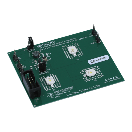
This user's guide describes the characteristics, operation, and use of the TPS61165EVM-283 evaluation
module (EVM). This EVM contains the Texas Instruments TPS61165 boost converter, configured with
external components to regulate current through a string of WLEDs. This user's guide includes EVM
specifications, recommended test setup, test results, bill of materials, and a schematic diagram.
..................................................................................................................
1
2
3
4
1
2
Screen Capture of TPS6116x Controller Software GUI Interface
3
LED Efficiency vs Output Current
4
5
6
1
Typical Performance Specification Summary
2
HPA283 Bill of Materials
SLVU224C - January 2008 - Revised February 2010
Submit Documentation Feedback
....................................................................................................
................................................................................................................
..........................................................................................
.........................................................................................
.............................................................................................................
..............................................................................................................
..........................................................................................................
..................................................................................................
Copyright © 2008-2010, Texas Instruments Incorporated
SLVU224C - January 2008 - Revised February 2010
TPS61165EVM-283
Contents
List of Figures
....................................................................
....................................................
List of Tables
...........................................................................
User's Guide
2
2
6
9
4
6
6
7
8
9
2
10
1
TPS61165EVM-283
Advertisement

Subscribe to Our Youtube Channel
Related Manuals for Texas Instruments TPS61165EVM-283


Summary of Contents for Texas Instruments TPS61165EVM-283
-
Page 1: Table Of Contents
SLVU224C – January 2008 – Revised February 2010 TPS61165EVM-283 This user's guide describes the characteristics, operation, and use of the TPS61165EVM-283 evaluation module (EVM). This EVM contains the Texas Instruments TPS61165 boost converter, configured with external components to regulate current through a string of WLEDs. This user's guide includes EVM specifications, recommended test setup, test results, bill of materials, and a schematic diagram. -
Page 2: Introduction
Introduction The Texas Instruments TPS61165EVM-283 evaluation module contains a TPS61165 IC, supporting active and passive components and three white light-emitting diodes (WLEDs) in series. The goal of this EVM is to facilitate evaluation of the TPS61165 in a typical WLED application. - Page 3 Windows™ 2000 or Windows™ XP operating system • USB port • Minimum of 30 MB of free hard disk space (100 MB recommended) SLVU224C – January 2008 – Revised February 2010 TPS61165EVM-283 Submit Documentation Feedback Copyright © 2008–2010, Texas Instruments Incorporated...
-
Page 4: Usb Interface Adapter Quick Connection Diagram
Computer 10-Pin Ribbon Cable Interface Adapter USB Cable Green LED Indicates Power EVM Board Figure 1. USB Interface Adapter Quick Connection Diagram TPS61165EVM-283 SLVU224C – January 2008 – Revised February 2010 Submit Documentation Feedback Copyright © 2008–2010, Texas Instruments Incorporated... - Page 5 Immediately following installation, the software automatically runs. To run the software after installation, go to Start → all programs → Texas Instruments, Inc. → TPS6116x Controller EVM Software. At start-up, the software first checks the firmware version of the USB-TO-GPIO adapter box. If an incorrect firmware version is installed, the software automatically searches on the Internet (if connected) for updates.
-
Page 6: Board Layout
Board Layout www.ti.com Figure 2. Screen Capture of TPS6116x Controller Software GUI Interface Test Results This section provides typical performance characteristics for the TPS61165EVM-283 board. I - Output Current - mA Figure 3. LED Efficiency vs Output Current Board Layout This section provides the TPS61165EVM-283 board layout and illustrations. -
Page 7: Assembly Layer
Figure 6 show the board layout for the TPS61165EVM-283 printed circuit board (PCB). The nodes with high-switching frequencies and currents are kept as short as possible to minimize trace inductance. Careful attention was given to the routing of high-frequency current loops and a single-point grounding scheme is used. See the data sheet for specific layout guidelines. -
Page 8: Top-Side Layer
Board Layout www.ti.com Figure 5. Top-Side Layer TPS61165EVM-283 SLVU224C – January 2008 – Revised February 2010 Submit Documentation Feedback Copyright © 2008–2010, Texas Instruments Incorporated... -
Page 9: Schematics And Bill Of Materials
Figure 6. Bottom-Side Layer Schematics and Bill of Materials This section provides the TPS61165EVM-283 schematic and bill of materials. The EVM was designed and tested assuming the input voltage is 5 V ±10%. Lower input voltages may result in the part entering current limit and therefore not providing the regulated current in the specification table. - Page 10 All other components can be substituted with equivalent MFG's components. 5. D2, D3, D4 can be any LW W5SM. The last eight characters of the orderable number are don't cares. TPS61165EVM-283 SLVU224C – January 2008 – Revised February 2010 Submit Documentation Feedback Copyright © 2008–2010, Texas Instruments Incorporated...
- Page 11 Schematics and Bill of Materials www.ti.com Related Documentation From Texas Instruments TPS61165, High Brightness White LED Driver in 2mm x 2mm QFN Package data sheet (SLVS790) SLVU224C – January 2008 – Revised February 2010 TPS61165EVM-283 Submit Documentation Feedback Copyright © 2008–2010, Texas Instruments Incorporated...
- Page 12 Evaluation Board/Kit Important Notice Texas Instruments (TI) provides the enclosed product(s) under the following conditions: This evaluation board/kit is intended for use for ENGINEERING DEVELOPMENT, DEMONSTRATION, OR EVALUATION PURPOSES ONLY and is not considered by TI to be a finished end-product fit for general consumer use. Persons handling the product(s) must have electronics training and observe good engineering practice standards.
- Page 13 IMPORTANT NOTICE Texas Instruments Incorporated and its subsidiaries (TI) reserve the right to make corrections, modifications, enhancements, improvements, and other changes to its products and services at any time and to discontinue any product or service without notice. Customers should obtain the latest relevant information before placing orders and should verify that such information is current and complete.
Need help?
Do you have a question about the TPS61165EVM-283 and is the answer not in the manual?
Questions and answers