Table of Contents
Advertisement
Quick Links
This user's guide describes the characteristics, operation, and use of the
TPS6105xEVM-141 evaluation module (EVM). This EVM demonstrates the Texas
Instruments TPS6105x synchronous boost converter with down mode used to power
high-current, white-light LEDs for photo flash applications. This user's guide includes
setup instructions, a schematic diagram, a bill of materials (BOM), and PCB layout
drawings for the evaluation module.
1
2
3
4
5
1
2
3
4
5
6
7
8
9
10
11
1
2
1
Introduction
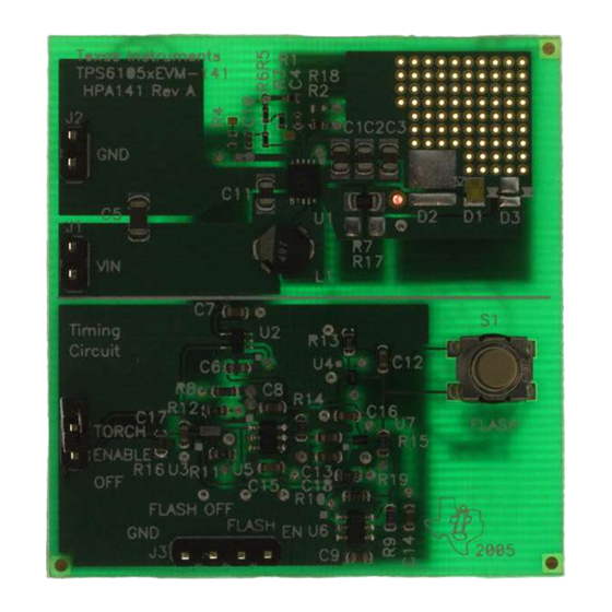
The Texas Instruments TPS6105xEVM-141 evaluation module (EVM) helps designers evaluate the
operation and performance of the TPS61058 or TPS61059 high-current boost converters for white-light
photo flash applications. The TPS6105x has an externally programmed LED current so that the LED can
be used as a flash for still photography and as a torch, or movie light, for digital movies.
The EVM has one white-flash LED, the TPS6105x converter, and a timing circuit used to make the EVM a
stand-alone flash module.
If desired, other LEDs or LED current settings can be tested on the EVM by changing the feedback
resistors on the EVM. See the TPS6105x data sheet for information on calculating new resistor values.
SLVU150 - January 2006
..........................................................................................
.................................................................................................
......................................................................................
.................................................................
..........................................................................
.............................................................................................
...................................................................................
................................................................................
............................................................................
.................................................................
....................................................................................
........................................................................
............................................
List of Figures
..........................................................
...........................................
..........................................................
....................................................
.................................................
List of Tables
User's Guide
SLVU150 - January 2006
TPS61059EVM-141
TPS61059EVM-141
1
2
10
12
14
4
5
6
7
8
9
9
10
11
12
13
2
14
1
Advertisement
Table of Contents

Subscribe to Our Youtube Channel
Related Manuals for Texas Instruments TPS61059EVM-141


Summary of Contents for Texas Instruments TPS61059EVM-141
-
Page 1: Table Of Contents
HPA141A Bill of Materials Introduction The Texas Instruments TPS6105xEVM-141 evaluation module (EVM) helps designers evaluate the operation and performance of the TPS61058 or TPS61059 high-current boost converters for white-light photo flash applications. The TPS6105x has an externally programmed LED current so that the LED can be used as a flash for still photography and as a torch, or movie light, for digital movies. -
Page 2: Setup
If JP1 is left open, the LED is off. If the FLASH button is pushed with JP1 open, then the LED flashes and returns to the off state after the flash time. TPS61059EVM-141 SLVU150 – January 2006... - Page 3 5. Push the FLASH button to flash the LED. 6. The LED flashes for approximately 320 ms. 7. If JP1 is shorted, then the LED returns to torch mode. If JP1 is open, the LED turns off. SLVU150 – January 2006 TPS61059EVM-141...
-
Page 4: Timing From Led Off To 700-Ma Flash
/FLASH LED Current NOTE: CH1 = Enable Signal – pin 1 of J3; CH2 = Flash Signal – Pin 2 of J3; CH4 = LED Current Figure 1. Timing From LED Off to 700-mA Flash TPS61059EVM-141 SLVU150 – January 2006... -
Page 5: Timing From 200-Ma Movie Light To 700-Ma Flash
LED Current NOTE: CH1 = Enable Signal – pin 1 of J3; CH2 = Flash Signal – Pin 2 of J3; CH4 = LED Current Figure 2. Timing From 200-mA Movie Light to 700-mA Flash SLVU150 – January 2006 TPS61059EVM-141... -
Page 6: Timing From Led Off To 700-Ma Flash
/FLASH LED Current NOTE: CH1 = Enable Signal – pin 1 of J3; CH2 = Flash Signal – Pin 2 of J3; CH4 = LED Current Figure 3. Timing From LED Off to 700-mA Flash TPS61059EVM-141 SLVU150 – January 2006... -
Page 7: Timing Between Flashes
Setup /FLASH LED Current NOTE: CH1 = Enable Signal – pin 1 of J3; CH2 = Flash Signal – Pin 2 of J3; CH4 = LED Current Figure 4. Timing Between Flashes SLVU150 – January 2006 TPS61059EVM-141... -
Page 8: Timing Between Flashes Using Pushbutton
NOTE: CH1 = Enable Signal – pin 1 of J3; CH2 = Flash Signal – pin 2 of J3; CH3 = Pushbutton Signal pin A1 of Figure 5. Timing Between Flashes Using Pushbutton TPS61059EVM-141 SLVU150 – January 2006... -
Page 9: Led Flash Interrupted With Flash Off Input
NOTE: CH1 = FLASH– pin 2 of J3; CH2 = FLASH OFF – Pin 3 of J3; LED Current Figure 6. LED Flash Interrupted With FLASH OFF Input = 700 mA @ V = 4.1 V − Input Voltage − V Figure 7. Efficiency SLVU150 – January 2006 TPS61059EVM-141... -
Page 10: Board Layout
Board Layout Board Layout This section provides the TPS6105xEVM-141 board layout and illustrations. Layout Figure Figure 9, and Figure 10 show the board layout for the TPS6105xEVM-141 printed-circuit board. Figure 8. Assembly Layer TPS61059EVM-141 SLVU150 – January 2006... -
Page 11: Top Layer Routing
Board Layout Figure 9. Top Layer Routing SLVU150 – January 2006 TPS61059EVM-141... -
Page 12: Schematic And Bill Of Materials
Schematic and Bill of Materials Figure 10. Bottom Layer Routing Schematic and Bill of Materials This section provides the TPS6105xEVM-141 schematic and bill of materials. TPS61059EVM-141 SLVU150 – January 2006... -
Page 13: Tps6105Xevm-141 Schematic
Schematic and Bill of Materials Schematic Figure 11. TPS6105xEVM-141 Schematic SLVU150 – January 2006 TPS61059EVM-141... -
Page 14: Related Documentation From Texas Instruments
Related Documentation From Texas Instruments Bill of Materials Table 2. HPA141A Bill of Materials COUNT Ref Des Value Description Size Part Number 22 µF C1, C2, C3, C11 Capacitor, Ceramic, 6.3V, X5R, 20% 0805 C2012X5R0J226MTJ 0.1 µF Capacitor, Ceramic, 25V, X5R, 10%... - Page 15 EVM TERMS AND CONDITIONS Texas Instruments (TI) provides the enclosed Evaluation Module and related material (EVM) to you, the user, (you or user) SUBJECT TO the terms and conditions set forth below. By accepting and using the EVM, you are indicating that you have read, understand and agree to be bound by these terms and conditions.
- Page 16 EVM schematic located in the EVM User's Guide. When placing measurement probes near these devices during operation, please be aware that these devices may be very warm to the touch. Mailing Address: Texas Instruments, Post Office Box 655303, Dallas, Texas 75265 Copyright © 2006, Texas Instruments Incorporated TPS61059EVM-141...
- Page 17 TI product or service and is an unfair and deceptive business practice. TI is not responsible or liable for any such statements. Following are URLs where you can obtain information on other Texas Instruments products and application solutions:...
Need help?
Do you have a question about the TPS61059EVM-141 and is the answer not in the manual?
Questions and answers