
Subscribe to Our Youtube Channel
Related Manuals for Siemens SIMATIC NET RUGGEDCOM RSG2200


Summary of Contents for Siemens SIMATIC NET RUGGEDCOM RSG2200
- Page 1 All manuals and user guides at all-guides.com Installation Manual SIMATIC NET Rugged Ethernet Switches RUGGEDCOM RSG2200 Edition 01/2020 https://www.siemens.com...
- Page 2 All manuals and user guides at all-guides.com Preface Introduction Installing the Device SIMATIC NET Device Management Rugged Ethernet Switches RUGGEDCOM RSG2200 Communication Ports Technical Specifications Installation Manual Certification 01/2020 C79000-G8976-1043-15...
- Page 3 Note the following: WARNING Siemens products may only be used for the applications described in the catalog and in the relevant technical documentation. If products and components from other manufacturers are used, these must be recommend- ed or approved by Siemens. Proper transport, storage, installation, assembly, commissioning, operation and maintenance are required to ensure that the products operate safely and without any problems.
-
Page 4: Table Of Contents
Preface ............................v Related Documents ......................... v Accessing Documentation ....................... v Training ........................... v Customer Support ........................vi Contacting Siemens ........................ vi Introduction ........................... 1 Feature Highlights ....................1 Description ......................2 Required Tools and Materials ................. 3 Decommissioning and Disposal ................3 Cabling Recommendations .................. - Page 5 All manuals and user guides at all-guides.com Table of Contents Technical Specifications ...................... 31 Power Supply Specifications ................31 Failsafe Relay Specifications ................31 Supported Networking Standards ................ 31 Copper Ethernet Port Specifications ..............32 Fiber Optic Ethernet Port Specifications ............... 33 Operating Environment ..................
-
Page 6: Preface
Siemens Customer Support. Training Siemens offers a wide range of educational services ranging from in-house training of standard courses on networking, Ethernet switches and routers, to on-site cus- tomized courses tailored to the customer's needs, experience and application. -
Page 7: Customer Support
All manuals and user guides at all-guides.com Preface Customer Support Customer Support Customer support is available 24 hours, 7 days a week for all Siemens customers. For technical support or general information, contact Siemens Customer Support through any of the following methods: Online Visit http://www.siemens.com/automation/support-request... -
Page 8: Introduction
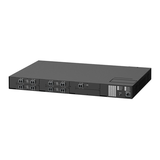
All manuals and user guides at all-guides.com Introduction The RUGGEDCOM RSG2200 is a rugged, fully managed, modular Ethernet switch specifically designed to operate reliably in electrically harsh and climatically de- manding utility substation, railway and industrial environments. The RUGGEDCOM RSG2200’s superior rugged hardware design coupled with the embedded Rugged Operating System (ROS) provides improved system reliability and advanced cyber security and networking features, making it ideally suited for creating Ethernet net- works for mission-critical, real-time, control applications. -
Page 9: Description
All manuals and user guides at all-guides.com Introduction 1.2 Description • CSA/UL 60950-1 safety approved to 85 °C (185 °F) Description The RUGGEDCOM RSG2200 features various ports, controls and indicator LEDs on the display panel for connecting, configuring and troubleshooting the device. The dis- play panel can be located on the rear, front or top of the device, depending on the mounting configuration. -
Page 10: Required Tools And Materials
All manuals and user guides at all-guides.com Introduction 1.3 Required Tools and Materials Mode Button The Mode button sets the display mode for the port status indicator LEDs (i.e. Status, Duplex or Speed). It can also be used to reset the device if held for 5 seconds. -
Page 11: Cabling Recommendations
Siemens also does not recommend using copper Ethernet ports to interface with de- vices in the field across distances that could produce high levels of ground potential rise (i.e. -
Page 12: Supported Fiber Optic Cables
All manuals and user guides at all-guides.com Introduction 1.5.3 Supported Fiber Optic Cables • Shielded/screened cabling can be used when required. Care should be taken to avoid the creation of ground loops with shielded cabling. 1.5.3 Supported Fiber Optic Cables The following fiber optic cable types are supported under the stated conditions. Cable Type Wavelength (nm) Modal Band-... - Page 13 All manuals and user guides at all-guides.com Introduction 1.5.3 Supported Fiber Optic Cables RUGGEDCOM RSG2200 Installation Manual, 01/2020, C79000-G8976-1043-15...
-
Page 14: Installing The Device
This product contains no user-serviceable parts. Attempted service by unauthorized personnel shall render all warranties null and void. Changes or modifications not expressly approved by Siemens AG could invalidate specifications, test results, and agency approvals, and void the user's authority to operate the equipment. -
Page 15: Unpacking The Device
Visually inspect each item in the package for any physical damage. Verify all items are included. NOTICE If any item is missing or damaged, contact Siemens for assistance. Mounting the Device The RUGGEDCOM RSG2200 is designed for maximum mounting and display flexibili- ty. -
Page 16: 2.3.1 Mounting The Device To A Rack
All manuals and user guides at all-guides.com Installing the Device 2.3.1 Mounting the Device to a Rack 2.3.1 Mounting the Device to a Rack The RUGGEDCOM RSG2200 can be secured to a standard 48 cm (19 in) rack using separately purchased rack mount adapters. The adapters can be installed at the front or rear of the chassis. -
Page 17: Mounting The Device On A Din Rail
All manuals and user guides at all-guides.com Installing the Device 2.3.2 Mounting the Device on a DIN Rail Make sure the rack mount adapters are installed on the correct side of the chas- sis. • To make the modules and ports accessible, install the rack mount adapters at the rear of the chassis •... -
Page 18: 2.3.3 Mounting The Device To A Panel
All manuals and user guides at all-guides.com Installing the Device 2.3.3 Mounting the Device to a Panel To mount the device to a DIN rail, do the following: Align the adapters with the DIN rails and slide the device into place. Panel/DIN Rail Adapter DIN Rail Screw... -
Page 19: Connecting The Failsafe Alarm Relay
All manuals and user guides at all-guides.com Installing the Device 2.4 Connecting the Failsafe Alarm Relay To mount the device to a panel, do the following: Place the device against the panel and align the adapters with the mounting holes. Screw Panel/DIN Rail Adapter Figure 2.3 Panel Mounting... -
Page 20: Connecting Power
All manuals and user guides at all-guides.com Installing the Device 2.5 Connecting Power Normally Open Common Normally Closed Figure 2.4 Failsafe Alarm Relay Wiring Connecting Power The RUGGEDCOM RSG2200 supports a single or dual redundant AC and/or DC power supplies. The RUGGEDCOM RSG2200 can be equipped with either a screw-type or pluggable terminal block, which provides power to both power supplies . -
Page 21: Connecting Ac Or Dc Power
All manuals and user guides at all-guides.com Installing the Device 2.5.1 Connecting AC or DC Power • It is recommended to provide a separate circuit breaker for each power supply module. • Equipment must be installed according to applicable local wiring codes and stan- dards. - Page 22 All manuals and user guides at all-guides.com Installing the Device 2.5.1 Connecting AC or DC Power Connect the positive wire from the power source to the positive/live (+/L) termi- nal on the terminal block. Screw-Type Terminal Block Pluggable Terminal Block Jumper Positive/Live (+/L) Terminal Negative/Neutral (-/N) Terminal (-/N) Surge Ground Terminal...
-
Page 23: 2.5.2 Wiring Examples
All manuals and user guides at all-guides.com Installing the Device 2.5.2 Wiring Examples Using a #6 ring lug and #6-32 screw, secure the ground terminal on the power source to the chassis ground terminal on the device. Make sure the lug is tight- ened to 1.7 N·m (15 lbf·in). - Page 24 All manuals and user guides at all-guides.com Installing the Device 2.5.2 Wiring Examples Figure 2.7 Single AC Power Supply Figure 2.8 Single DC Power Supply RUGGEDCOM RSG2200 Installation Manual, 01/2020, C79000-G8976-1043-15...
- Page 25 All manuals and user guides at all-guides.com Installing the Device 2.5.2 Wiring Examples Figure 2.9 Dual AC Power Supply Figure 2.10 Dual DC Power Supply RUGGEDCOM RSG2200 Installation Manual, 01/2020, C79000-G8976-1043-15...
- Page 26 All manuals and user guides at all-guides.com Installing the Device 2.5.2 Wiring Examples Figure 2.11 Dual AC/DC Power Supply RUGGEDCOM RSG2200 Installation Manual, 01/2020, C79000-G8976-1043-15...
- Page 27 All manuals and user guides at all-guides.com Installing the Device 2.5.2 Wiring Examples RUGGEDCOM RSG2200 Installation Manual, 01/2020, C79000-G8976-1043-15...
-
Page 28: Device Management
All manuals and user guides at all-guides.com Device Management This section describes how to connect to and manage the device. Connecting to the Device The following describes the various methods for accessing the RUGGEDCOM RSG2200 console and Web interfaces on the device. For more detailed instructions, refer to the RUGGEDCOM RSG2200 User Guide for the RUGGEDCOM RSG2200. -
Page 29: Configuring The Device
All manuals and user guides at all-guides.com Device Management 3.2 Configuring the Device Name Description Comment RJ45 Male DB9 Female Ring Indicator The DSR, DCD and DTR pins are connected together internally. The CTS and RTS pins are connected together internally. RI is not connected. -
Page 30: Communication Ports
All manuals and user guides at all-guides.com Communication Ports The RUGGEDCOM RSG2200 can be equipped with various types of communication ports to enhance its abilities and performance. With five available slots, the RUGGED- COM RSG2200 supports a variety of one- or two-port fiber or copper Ethernet module of various speeds with up to nine Gigabit Ethernet (1 Gbps) ports. -
Page 31: Copper Ethernet Ports
All manuals and user guides at all-guides.com Communication Ports 4.1 Copper Ethernet Ports LED State Description Yellow (Solid) Link established Yellow (Blinking) Link activity No link detected Port LED Figure 4.2 Port LEDs Copper Ethernet Ports The RUGGEDCOM RSG2200 supports several 10/100/1000Base-TX Ethernet ports that allow connection to standard Category 5 (CAT-5) unshielded twisted-pair (UTP) ca- bles with either RJ45 male connectors. -
Page 32: Fiber Optic Ethernet Ports
All manuals and user guides at all-guides.com Communication Ports 4.2 Fiber Optic Ethernet Ports Name Description 10/100Base-TX 1000Base-TX BI_DB+ Transmit Data+ or Bi- Directional Pair B+ Reserved (Do Not Connect) BI_DC+ Transmit Data+ or Bi- Directional Pair C+ Reserved (Do Not Connect) BI_DC- Receive Data- or Bi- Directional Pair C-... -
Page 33: Sfp Transceivers
RUGGEDCOM SFP Transceiver Catalog [https://support.indus- try.siemens.com/cs/ww/en/view/109482309] NOTICE Only use SFP transceivers approved by Siemens for RUGGEDCOM products. Siemens accepts no liability as a result of performance issues related in whole or in part to third-party components. SFP Transceiver... -
Page 34: Gbic Optic Ethernet Ports
To install a GBIC optical port, do the following: CAUTION Electrical hazard – risk of damage to equipment Use only components certified by Siemens with RUGGEDCOM products. Damage to the module and device may occur if compatibility and reliability have not been prop- erly assessed. - Page 35 All manuals and user guides at all-guides.com Communication Ports 4.4.1 Installing a GBIC Optical Port Remove the port from its packaging. CAUTION Mechanical hazard – risk of component damage GBIC optical ports are designed to insert in only one orientation. Do not force the port into the module.
-
Page 36: 4.4.2 Removing A Gbic Optical Port
All manuals and user guides at all-guides.com Communication Ports 4.4.2 Removing a GBIC Optical Port 4.4.2 Removing a GBIC Optical Port To remove an GBIC optical port, do the following: CAUTION Electrical hazard – risk of damage to equipment Make sure all electrostatic energy is dissipated before performing installing or re- moving components from the device. - Page 37 All manuals and user guides at all-guides.com Communication Ports 4.4.2 Removing a GBIC Optical Port RUGGEDCOM RSG2200 Installation Manual, 01/2020, C79000-G8976-1043-15...
-
Page 38: Technical Specifications
All manuals and user guides at all-guides.com Technical Specifications This section details the specifications and operating conditions of the device. Power Supply Specifications The RUGGEDCOM RSG2200 can be equipped with the following power supplies: CAUTION Electrical hazard – risk of damage to the device Make sure power input to the device is within the specified input range. -
Page 39: Copper Ethernet Port Specifications
Note • Maximum segment length is greatly dependent on factors such as fiber quality, and the number of patches and splices. Consult a Siemens sales associate when determining maximum segment distances. • All optical power numbers are listed as dBm averages. -
Page 40: Fiber Optic Ethernet Port Specifications
1310 Typical. Typical distance. The maximum distance is greatly dependent on factors such as cable type, the number of connectors and number of splices. Consult a Siemens sales associates when determining maximum distances. Gigabit Ethernet (1 Gbps) Optical Specifications Note These transceivers utilize a distributed feedback (DFB) type laser and are rated for -20 to 85 °C (-4 to 185 °F) operation only. -
Page 41: Operating Environment
5.6 Operating Environment Typical distance. The maximum segment length is greatly dependent on factors such as fiber quality, and the number of patches and splices. Consult a Siemens sales associates when determining maximum segment distances. GBIC Gigabit (1 Gbps) Transceiver Specifications Note GBIC transceivers have a temperature range of -40 to 85 °C (-40 to 185 °F), unless... -
Page 42: Dimension Drawings
All manuals and user guides at all-guides.com Technical Specifications 5.8 Dimension Drawings Dimension Drawings Note All dimensions are in millimeters, unless otherwise stated. Note Dimensional tolerances are in accordance with ISO 2768-mK, unless otherwise stat- 438.15 Figure 5.1 Overall Dimensions RUGGEDCOM RSG2200 Installation Manual, 01/2020, C79000-G8976-1043-15... - Page 43 All manuals and user guides at all-guides.com Technical Specifications 5.8 Dimension Drawings 32.77 21.08 11.68 479.29 478.79 4.57 Figure 5.2 Rack Mount Dimensions RUGGEDCOM RSG2200 Installation Manual, 01/2020, C79000-G8976-1043-15...
- Page 44 All manuals and user guides at all-guides.com Technical Specifications 5.8 Dimension Drawings 11.7 10.4 476.3 486.4 Figure 5.3 Panel and DIN Rail Mount Dimensions RUGGEDCOM RSG2200 Installation Manual, 01/2020, C79000-G8976-1043-15...
- Page 45 All manuals and user guides at all-guides.com Technical Specifications 5.8 Dimension Drawings RUGGEDCOM RSG2200 Installation Manual, 01/2020, C79000-G8976-1043-15...
-
Page 46: Certification
UL 60950-1 Information Technology Equipment – Safety Part 1: General Requirements 6.1.2 European Union (EU) This device is declared by Siemens AG to comply with essential requirements and other relevant provisions of the following EU directives: • EN 60950-1 Information Technology Equipment – Safety – Part 1: General Requirements •... -
Page 47: Fcc
Methods of Measurement The device is marked with a CE marking and can be used throughout the European community. A copy of the CE Declaration of Conformity is available from Siemens AG. For contact information, refer to "Contacting Siemens (Page vi)". -
Page 48: 6.1.6 Iso
Quality management systems – Requirements 6.1.7 RoHS This device is declared by Siemens AG to meet the requirements of the following Ro- HS (Restriction of Hazardous Substances) directives for the restricted use of certain hazardous substances in electrical and electronic equipment: •... - Page 49 All manuals and user guides at all-guides.com Certification 6.2 EMC and Environmental Type Tests EMC Type Tests per IEC 61850-3 Note • In the case of an all fiber port configuration, this product meets all Class 2 re- quirements. Otherwise, all Class 1 requirements are met for copper ports. •...
- Page 50 5 kV AC Power Ports Siemens-specified severity levels EMC Immunity Type Tests per IEEE 1613 Note The RUGGEDCOM RSG2200 meets Class 2 requirements for an all-fiber configuration and Class 1 requirements for copper ports. Class 1 allows for temporary communica- tion loss, while Class 2 requires error-free and interrupted communications.
- Page 51 All manuals and user guides at all-guides.com Certification 6.2 EMC and Environmental Type Tests Description Test Levels Dielectric Signal Ports 2 kV Strength DC Power Ports 2 kV AC Power Ports 2 kV Damped Os- Enclosure Ports 100 A/m cillatory Mag- netic Field Environmental Type Tests Test...
- Page 52 All manuals and user guides at all-guides.com Further Information Siemens RUGGEDCOM https://www.siemens.com/ruggedcom Industry Online Support (service and support) https://support.industry.siemens.com Industry Mall https://mall.industry.siemens.com Siemens AG Digital Industry Process Automation Postfach 48 48 90026 NÜRNBERG GERMANY...
Need help?
Do you have a question about the SIMATIC NET RUGGEDCOM RSG2200 and is the answer not in the manual?
Questions and answers