iOptron CEM40 Instruction Manual
Center-balanced equatorial mount
Hide thumbs
Also See for CEM40:
- Instruction manual (55 pages) ,
- Replacement (2 pages) ,
- Quick start manual (8 pages)

Related Manuals for iOptron CEM40


Summary of Contents for iOptron CEM40
- Page 1 ® iOptron Center-Balanced Equatorial Mount Instruction Manual Product CEM40, CEM40G, CEM40EC and CEM40-NUC (C40XXX)
- Page 2 Please read the included CEM40 Quick Setup Guide (QSG) BEFORE taking the mount out of the case! This product is a precision instrument. Please read the included QSG before assembling the mount. Please read the entire Instruction Manual before operating the mount.
-
Page 3: Table Of Contents
2.3.1. Ports on Main Control Board ......................7 2.3.2. Other Ports on a CEM40G Mount ....................8 2.3.3. Other Ports on a CEM40/CEM40EC Mount ..................9 2.3.4. Other Ports on a CEM40-NUC/CEM40EC-NUC Mount .............. 10 2.3.5. Pass-through Hole .......................... 11 ®... - Page 4 Appendix H. Computer Control a CEM40 Mount ................... 59 IOPTRON TWO YEAR TELESCOPE, MOUNT, AND CONTROLLER WARRANTY ......60 Ver. 3.1 2023.01 iOptron reserves the rights to revise this instruction without notice. Actual color/contents/design/function may differ from those described in this instruction manual.
-
Page 5: Cem40 Introduction
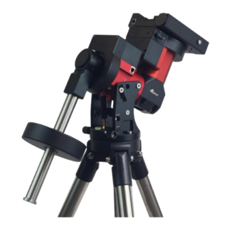
Make way for an innovative mount! iOptron CEM40G mount has a built-in iGuider guiding camera. The mount has a 6” dual saddle that accommodates Losmandy and Vixen-style dovetail plates.. The CEM40 also uses iOptron's ultra-quiet, low-power consumption stepper motor drive system, aiding the mount in providing precise tracking. -
Page 6: Cem40G Overview
2.1. Parts List SHIPPING CONTENTS Your new CEM40 mount comes in three shipping boxes. One box contains a CEM40 mount head, hand controller, counterweight shaft, and accessories. One box contains a tripod. Third box is an 11lbs counterweight (#8027). The contents are: ... -
Page 7: Identification Of Parts
HBX (Hand Box): For connecting to a Go2Nova Hand Controller iPORT: Auxiliary port for connecting to other iOptron accessories, such as a GPS receiver, an iStarFi wi-fi adapter, an electronic focuser or for observatory dome control. DO NOT plug ST-4... -
Page 8: Other Ports On A Cem40G Mount
2.3.2. Other Ports on a CEM40G Mount Power Panel on Rear of RA axis Figure 3. CEM40G Power Panel on Rear of RA axis POWER (I/O): Power Switch DC 12V 5A: DC power socket to power the mount (2.5mmX5.5mm, center positive) ... -
Page 9: Other Ports On A Cem40/Cem40Ec Mount
USB2.0: USB input port to connect to iPolar, iGuider, USB 2.0 Port on dovetail saddle, as well as mount computer control and firmware upgrade. Ports on the Dovetail Saddle Figure 8. Ports on a CEM40/CEM40EC dovetail saddle On the back of the dovetail saddle, there are following ports: ... -
Page 10: Other Ports On A Cem40-Nuc/Cem40Ec-Nuc Mount
2.3.4. Other Ports on a CEM40-NUC/CEM40EC-NUC Mount Power Panel on Rear of RA axis Figure 9. CEM40-NUC Input Panel on Rear of RA axis NUC DC19V: Pass through for NUC power input. Connect the AC adapter come with NUC, 19V, or 12V for some later model. -
Page 11: Pass-Through Hole
Figure 10. Cable/Ports connection of a CEM40-NUC DC OUTX3:DC outlets,total current 5A, 2.1/5.5 mm plug, powered by cable management input GUIDE:Guiding port, support ST-4 guiding device/camera Suggested Intel NUC Those NUC with thickness less than 38mm with be fit onto the mount without interference with the mount body, such as Intel Frost Canyon or Tiger Canyon with “Slim”... -
Page 12: Go2Nova Hand Controller
Either Go2Nova 8407+ or 8410 hand controller (HC) works with a CEM40 mount. Shown in Figure 12 is an 8410 HC. The difference between an 8407+ and an 8410 is if there is a RS232 port on the HC for firmware upgrade. -
Page 13: The Lcd Screen
STOP/0 Key: Stop the mount during GOTO. Also toggling between starting and stopping tracking. HBX (Handbox) port: connect the HC to the CEM40 mount using a 6P6C RJ11 cable. 2.4.2. The LCD Screen The Go2Nova HC has a large 8-line, 21-character per line, LCD screen which displays information on the status of the mount as shown in Figure 13.The user interface is simple and easy to operate. -
Page 14: Install And Check The Hand Controller Battery
11. PEC status: Display of “PEC” here Indicates the Periodic Error Correction playback is turned on. Default is off. 12. Tracking speed: Displays the current tracking rate of the mount. SDRL: mount is tracking at sidereal speed; Solar: mount is tracking at solar speed; ... -
Page 15: Cem40 Mount Assembly
3. CEM40 Mount Assembly 3.1. CEM40 Mount Assembly NOTE: The CEM40 mount is a precision astronomical instrument. It is highly recommended that you read this entire manual and become familiar with the nomenclature and function of all components before starting assembly. - Page 16 STEP 3. Attach the mount Retract the 2x Azimuth (Azi) Adjustment Screws from both sides to leave ample space for the alignment peg to fit in between the 2 Azi Adjustment Screws. Remove the 2x Azi Locking Screws, with washers, from the mount base. Secure the mount head by tightening the Azi Locking Screws into the M6 holes on the tripod.
- Page 17 Figure 20. Change latitude range STEP 5. Install Counterweight (CW) Shaft Thread the CW shaft into the CW shaft mounting house. For low latitudes (<10°), a special CW mounting house is needed. (Contact iOptron for more information) Figure 21. Install CW shaft...
- Page 18 You may need more CW for heavier payloads, or a smaller CW for lighter scopes. CEM40 is equipped with a Vixen/Losmandy-D dual saddle. It can receive either a Vixen or a Losmandy-D plate. Release the dovetail saddle locking knobs and slide the telescope dovetail plate into the saddle.
- Page 19 Figure 23. Balance a mount Return the mount to Zero Position after balancing and engage gear switches. STEP 8. Connect Cables Plug in included 12V/5A DC power supply to the DC12V 5A socket, which is located at the end of the RA axis.
- Page 20 STEP 9. Setting up the Hand Controller The CEM40 mount is equipped with a GPS receiver which will receive the time, longitude and latitude information for your current location from satellites after a link is established. However, there are still some parameters which need to be entered to reflect your location, such as time zone information and whether daylight saving time is currently in effect.
- Page 21 STEP 11. Perform Polar Alignment Polar Alignment with iPolar Electronic Polar Scope CEM40 are equipped with an iPolar electronic polar scope. Plug a USB cable into the USB port on the rear end of the mount RA axis to connect the iPolar to a computer.
- Page 22 Download and install iPolar Software (first time use) Connect a USB cable between the mount and a computer USB port Start polar alignment by following on screen instructions Polar Alignment Software There are quite a few alignment software available for polar alignment, such as PHD2 guiding, TheSky software, PemPro, or Alignmaster.
-
Page 23: Cem40 Operation
4.5. Power-Down Memorization The CEM40 mount can memorize its R.A. and DEC positions if the mount power is lost during operation, even during high speed slewing. After the power is back, just do a Select and Slew to the same... -
Page 24: Turn Off The Mount
4.6. Turn Off the Mount When you have finished your observation, simply turn the mount power off and disassemble the mount and tripod. If the mount is set up on a pier or inside an observatory, it is recommended that you return the mount to the Zero Position or park the telescope. -
Page 25: Complete Functions Of Go2Nova Hand Controller
® 5. Complete Functions of Go2Nova Hand Controller 5.1. Select and Slew Press the MENU button. From the main menu select “Select and Slew”. Select an object that you would like to observe and press the ENTER key. ® hand controller has a database of around 212,000 objects. Use the ► or ◄ buttons The Go2Nova to move the cursor. -
Page 26: Custom Objects
5.3. Alignment 5.3.1. Position of Polaris/SigmaOct ® This function displays the position of the Pole Star in an iOptron AccuAlign polar scope. In the Northern Hemisphere the position of Polaris is displayed, while in the Southern Hemisphere the position of Sigma Octantis is shown. -
Page 27: Beep Settings
5.4.2. Beep Settings The Hand Controller allows a user to turn off the beep partially, or even go to a silent mode. To change this setting press “MENU =>Settings => Beep Settings”, Set Up Time and Site Beep Settings Display Settings Set Guiding Rates Set Tracking Rate Set Parking Position... -
Page 28: Set Tracking Rate
Losmandy/ Takahashi/ Vixen, make sure a proper guiding cable is used. Refer to your guiding camera and guiding software for detailed operation. WARNING: DO NOT plug your ST-4 guiding camera cable into the iOptron port or HBX port. It may damage the mount or guiding camera electronics. -
Page 29: Hc Heating Switch
Select one of supported menu languages. Currently it has English and Chinese. 5.5. Electric Focuser This function controls an iOptron electric focuser #8451 or #8452. It does not work for #8453 iEAF. 5.6. PEC Option This function only works for the CEM40/CEM40G mount, not for a mount with high precision encoder. -
Page 30: Pec Data Integrity
1. Setup the mount with a telescope in autoguiding configuration by connecting a guiding camera via the mount’s Guide Port or using the ASCOM protocol; 2. Select “MENU=>Settings => Set Guiding Rates”. Set a guiding speed from 0.10X to 0.90X. The default setting is 0.50X;... -
Page 31: Enter Other Objects Or Observation List
Enter Comet Parameter Date: 0000-00-00.0000 q: 0.000000 e: 0.000000 ω: 000.0000 Ω: 000.0000 i: 000.0000 Enter the parameters using the arrow buttons and number keys. Press ENTER and a confirmation screen will be displayed. Press ENTER again to store the object under the assigned user object number, or press BACK button to cancel. -
Page 32: Zero Position
To counter this, the CEM40 has been equipped with a function that can find the Zero Position for an initial mount set up. -
Page 33: Maintenance And Servicing
Department. Customer Service hours are from 9:00 AM to 5:00 PM, Eastern Time, Monday through Friday. In the event that the CEM40 requires factory servicing or repairing, write or call iOptron Customer Service Department first to receive a RMA# before returning the mount to the factory. Please provide details as to the nature of the problem as well as your name, address, e-mail address, purchase information and daytime telephone number. -
Page 34: Appendix A. Technical Specifications
Φ110mm, 216 teeth aluminum Right Ascension worm wheel Φ110mm, 216 teeth aluminum Declination worm wheel PPEC/Real time PEC <±7.5 arcsec p-p (CEM40, CEM40G), or Tracking accuracy (PE)** <0.3 arcsec RMS (CEM40EC) Φ28X280 mm, Stainless Steel (1.2 kg) Counterweight shaft Counterweight 11 lb (5 kg) X1 Φ120 mm... -
Page 35: Appendix B. Go2Nova
® Appendix B. Go2Nova HC MENU STRUCTURE MENU Select and Slew Solar System Mercury Venus Mars Jupiter Saturn Uranus Neptune Moon Deep Sky Objects Named Object Messier Catalog Caldwell Catalog Abell Catalog Herschel Catalog Stars Named Stars Double/Multi Stars Hipparcors Catalog Comets Asteroids Constellations... - Page 36 Alignment Position of Pole Star Polar Iterate Align Settings Set Time & Site Beep Settings Display Settings Set Guiding Rates Set Tracking Rate Autol Rate Custom Tracking Speed Set Parking Position Meridian Treatment Set Position Limit Set Behavior Set Altitude Limit Enable CW Up Pos.
- Page 37 Edit User Objects Custom Comets Add a New Comet Browse Comets Delete One Comet Delete All Comets Other Objects Add a New Object Browse Objects Delete One Object Delete All Objects Firmware Information Zero Position Goto Zero Position Set Zero position Search Zero Position...
-
Page 38: Appendix C. Go2Nova Star List
® Appendix C. Go2Nova Star List Named Deep Sky Object 47 Tucanae 47 Integral Sign Galaxy Andromeda Galaxy 48 Iris Nebula Antennae Galaxies 49 Jellyfish Nebula Barnard's Galaxy 50 Jewel Box Cluster Bear-Paw Galaxy 51 Lagoon Nebula Beehive Cluster 52 Lambda Centauri Nebula Black Eye Galaxy 53 Large Magellanic Cloud Blinking Planetary... - Page 39 Messier Catalog This table is licensed under the GNU Free Documentation License. It uses material from the Wikipedia article List of Messier objects...
- Page 40 Named Stars Acamar Alrescha Deneb el Okab Lalande 21185 Achernar Alshain Deneb Kaitos Lesath Achird Altair Denebakrab Mahasim Acrab Altais Denebola Maia Acrux A Alterf Dschubba Marfik Acrux B Aludra Dubhe Marfikent Acubens Alula Australis Edasich Markab Adhafera Alula Borealis El Rehla Markeb Adhara...
- Page 41 Proxima Centauri Sadalbari Sulafat Vindemiatrix Rasalas Sadalmelik Syrma Vrischika Rasalgethi Sadalsuud Talitha Wasat Rasalhague Sadr Tania Australis Wazn Rastaban Saiph Tania Borealis Regor Sargas Tarazed Wezen Regulus Scheat Taygeta Yed Posterior Rigel Schedar Tejat Posterior Yed Prior Rigel Kentaurus A Seginus Thuban Zaniah...
- Page 42 Modern Constellations Constellation Abbreviation Constellation Abbreviation Andromeda Lacerta Antlia Apus Leo Minor Aquarius Lepus Aquila Libra Lupus Aries Lynx Auriga Lyra Boötes Mensa Caelum Microscopium Camelopardalis Monoceros Cancer Musca Canes Venatici Norma Canis Major Octans Canis Minor Ophiuchus Capricornus Orion Carina Pavo Cassiopeia...
- Page 43 Double/Multi Stars HC Item Constellation Name Rigel Kentaurus A Alpha Centauri Centaurus 71683 14396-6050 252838 Rigel Beta Orionis Orion 24436 05145-0812 131907 Gacrux Gamma Crucis Crux 61084 12312-5707 240019 Sargas Theta Scorpii Scorpius 86228 17373-4300 228201 Castor A Alpha Geminorum Gemini 36850 07346+3153 60198...
- Page 44 HC Item Constellation Name 53 HIP 95771 Alpha Vulpeculae Vulpecula Anser 19287+2440 87261 54 HIP 30867 Beta Monocerotis Monoceros 06288-0702 133316 55 HIP 35363 NV Puppis Puppis 07183-3644 197824 56 HIP 94761 Gliese 752 Aquila Wolf 1055, Ross 652 19169+0510 57 HIP 21683 Sigma2 Tauri Taurus...
- Page 45 HC Item Constellation Name 105 HIP 40167 Zeta1 Cancri Cancer Tegmen 08122+1739 97645 106 HIP 40817 Kappa Volantis Volans 08198-7131 256497 107 HIP 81292 17 Draconis Draco 16362+5255 30013 108 HIP 80197 Nu1 Coronae Borealis Corona Borealis 16224+3348 65257 109 HIP 88060 HD 163756 Sagittarius 17591-3015...
- Page 46 HC Item Constellation Name 157 HIP 28790 HD 41742 Puppis 06047-4505 217706 158 HIP 4675 HD 5788 Andromeda 01001+4443 36832 159 HIP 31676 8 Lyncis Lynx 06377+6129 13897 160 HIP 10176 59 Andromedae Andromeda 02109+3902 55330 161 HIP 25950 HD 36408 Taurus 05322+1703 94630...
-
Page 47: Appendix D. Gear Meshing Adjustment
Tool needed: 2mm and 3mm hex keys. 1. Gear Switch iOptron Gear Switch uses a spring plunger to apply the force on worm assembly to push the worm against the ring gear for gear meshing. It has a tuning knob, body, threaded spring plunger, positioning spring and ball bearing. - Page 48 2. Spring plunger position related to meshing result Disengaged position Not touched. There will be free play Just touched. Minimum meshing force. No free play Engaged position. Normal operation position Plunger adjusted too much. Ball had been pushed all the way in and no spring loading power The gear switch should be adjusted to a position that between 2 and 4.
- Page 49 Rotate DEC saddle to exposure the small hole (3mm in diameter) that is blocked by the dovetail saddle. Another larger hole (5mm) is located on the side of the DEC gear housing. There is a set screw inside the 3mm hole which locks the gear meshing adjustment screw, which is inside the larger hole. Engage the worm/gear by turn the gear switch to locking position.
- Page 50 The RA gear meshing adjustment screw is located next to the RA Gear Switch. The adjustment is same as that for DEC gear/worm. DO NOT over tighten the gear meshing adjustment plunger to avoid damage it. Please contact support@ioptron.com if you need more information.
-
Page 51: Appendix E. Polar Alignment Using Ipolar Electronic Polar Scope
Plug a USB cable into the USB2.0 port on the rear end of mount RA axle to connect the iPolar to a computer. (2) The iPolar driver will be automatically installed if it is the first time connecting to the computer (3) You should see “iOptron iPolar” under Camera catalog in computer Device Manager (4) Goto www.ioptron.com to download iPolar software and save on your computer (5) The iPolar software needs Windows 7, 8.1, 10 or later version, 32 bit or 64 bit operation system,... -
Page 52: Appendix F. Iguider For Cem40G
1. Focus adjuster locking screw (2mm hex), 2.Focus adjuster, 3.Lens cover The iGuider only support ASCOM guiding (no ST-4 connection). Please install iGuider ASCOM driver from iOptron website. PHD2 guiding software also has the camera included. 1. Connect iGuider to a PC The iGuider guiding system is connected internally to the mount main USB port. - Page 53 Start the PHD2 to start New Profile Wizard: Click on Next. Select “iOptron iGuider (ASCOM Camera)” from the camera selection menu. PHD2 will fill the pixel size (3.75um) automatically, if the camera is connected to the computer Enter 120mm into guide scope focal length tab, and click Next.
- Page 54 Select a mount that connected to the computer via ASCOM from the dropdown menu. Here “iOptron CEM120/70/40/26,GEM45/28 Mount (ASCOM)” is selected. A default guiding speed is 0.5X. Click Next. In next Adaptive Optics Device setting window, select None and go to Next.
- Page 55 Make sure you remove the lens cover. You may also check the iGuider camera during daytime by checking Show Preview in iOptron iGuider ASCOM window. Adjust Exposure Time and focuser to show the image.
- Page 56 (1) Manually slew in DEC to expose the Locking Screw. Loosen it first. (2) Remove iGuider lens cover. (3) Run PHD2 software and select “iOptron iGuider (ASCOM Camera)” (4) Go to a bright star (5) Turn the Focus Adjuster CCW to loosen it a little bit. Slide the Focus Adjuster to adjust the focus and bring the star to be shown in the main window.
- Page 57 4. Specifications Guiding scope aperture 30mm Focal length 120mm Imaging sensor 1/3 in CMOS Pixel size 3.75µm Resolution 1280X960 Operation system Windows (driverless)
-
Page 58: Appendix G. Firmware Upgrade
Appendix G. Firmware Upgrade The firmware of a hand controller and mount control boards can be upgraded by the customer. Please check iOptron’s website, www.iOptron.com, under Support Documents of the CEM40 product page. -
Page 59: Appendix H. Computer Control A Cem40 Mount
Appendix H. Computer Control a CEM40 Mount The CEM40 mount can be controlled by a SmartPhone, a tablet or a computer. It is supported by two types of computer connections: Connect to a computer via USB port on the mount main board using a USB cable. You may... -
Page 60: Ioptron Two Year Telescope, Mount, And Controller Warranty
As a condition to the obligation of iOptron to repair or replace such product, the product must be returned to iOptron together with proof-of-purchase satisfactory to iOptron.
Need help?
Do you have a question about the CEM40 and is the answer not in the manual?
Questions and answers