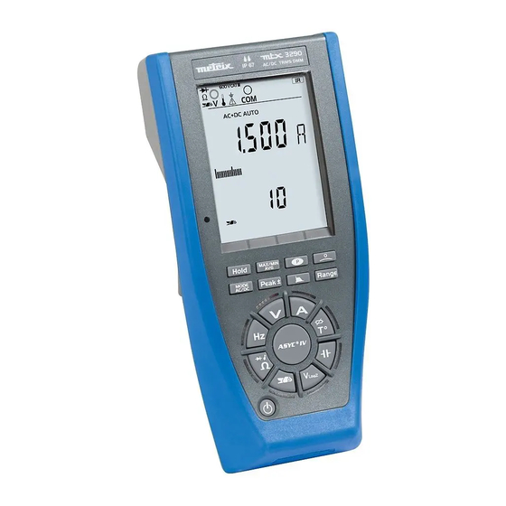
Metrix ASYC-IV Operating Instructions Manual
Portable multimeters with digital display
Hide thumbs
Also See for ASYC-IV:
- Operating instructions manual (62 pages) ,
- Quick start manual (30 pages)

Related Manuals for Metrix ASYC-IV


Summary of Contents for Metrix ASYC-IV
- Page 1 Operating instructions Pôle Test et Mesure CHAUVIN ARNOUX GlobalTestSupply www. .com Find Quality Products Online at: sales@GlobalTestSupply.com...
-
Page 2: Table Of Contents
General directions Contents General directions ............................3 Introduction, Precautions and safety measures ......................3 Special functions ................................4 Symbols on the instrument ............................5 Warranty, Maintenance, metrological verification, Repair under warranty ..............6 Maintenance .................................. 7 Replacing the fuse ................................. 7 Rechargeable and primary batteries .......................... -
Page 3: General Directions
General directions General directions Congratulations! You have just acquired a portable multimeter with a Introduction display digital. We thank you for this sign of confidence in the quality of our products. The line of instruments to which it belongs comprises the following models: MTX 3290 MTX 3291 Display... -
Page 4: Special Functions
General directions General directions (continued) It is impossible to open the battery or fuse compartment without first Safety feature disconnecting the measurement leads. During a measurement exceeding 60V or 25V symbol blinks on the display unit Automatic detection of a connection to the "Ampere" terminal (for both voltage and current measurements) When the maximum permanent voltage or current that can be measured is exceeded, an intermittent audible signal warns of the risk of an electric... -
Page 5: Symbols On The Instrument
General directions General directions (continued) Definitions of the CAT II: Test and measurement circuits directly connected to the points of use measurement of the low-voltage network (power outlets and other similar points). categories E.g.: Measurements on the network circuits of household appliances, portable tools, and similar devices. -
Page 6: Warranty, Maintenance, Metrological Verification, Repair Under Warranty
General directions General directions (continued) This equipment is warranted for 3 years against any defect of materials or Warranty workmanship, in accordance with the general terms of sale. During the warranty period, the instrument may be repaired only by the manufacturer, who reserves the right to repair the instrument or to replace it or part of it. -
Page 7: Maintenance
General directions General directions (continued) Maintenance Disconnect everything connected to the instrument and press the ON/OFF key ( Use a soft cloth, moistened with soapy water. Rinse with a damp cloth and dry rapidly with a dry cloth or forced air. Make sure that no foreign objects interfere with the operation of the device by which the leads are snapped into place. -
Page 8: Description Of The Instruments
Description of the instruments Description of the instruments MTX 3290 Frontal panel Back Prop Terminal block Optical connector: not active ! 6,000- and 60,000-count digital multimeters GlobalTestSupply www. .com Find Quality Products Online at: sales@GlobalTestSupply.com... -
Page 9: Mtx 3291 Frontal Panel, Back, Terminal Block
Description of the instruments Description of the instruments (continued) MTX 3291 Frontal panel Back Prop Terminal block Optical connector: active! 6,000- and 60,000-count digital multimeters GlobalTestSupply www. .com Find Quality Products Online at: sales@GlobalTestSupply.com... -
Page 10: Display Unit
Description of the instruments Description of the instruments (continued) Display unit The display is in two parts: A digital display for convenient reading of the digits: - main display unit: 12.7mm - secondary display unit: 9.7mm The "bargraph" display (61 segments) with scale (indication of the measurement range) for an analogue reading MTX 3291 MTX3290... - Page 11 Description of the instruments Description of the instruments (continued) Symbols Designation Measurement of the AC signal Measurement of the DC signal Measurement of the AC and DC signal Automatic range switching Values relative to a reference Reference value Storage and display of stored values Value (surveillance) Maximum value Minimum value...
- Page 12 Description of the instruments Description of the instruments (continued) This symbol indicates the battery charge level. Volt, Ohm, temperature, etc. measurement input COM measurement input Ampere measurement input 600V CAT III Input indication 1000V CAT III Input indication Isolated optical link (USB) input Display of unit on the main display unit (2x14 segments) Display of unit on the secondary display unit (2x14 segments) Identifies the reminder of the display zone connection...
-
Page 13: Switch
Description of the instruments Description of the instruments (continued) Switch Orange LEDs around the highly reliable virtual switch indicate the measurement function chosen. The keys of the switch have priority over the action of the keys of the keypad. The change from one function to another resets the configuration of the measurement mode. - Page 14 Description of the instruments Description of the instruments (continued) MTX 3291 Short press Successive short presses Keys of the switch Current measurement Selection of the type of probe: Temperature measurement Pt100, Pt1000 Capacitance measurement Low-impedance AC voltage measurement (VLowZ) Current measurement using a Selection of the transformation ratios current clamp 1, 10, 100, 1,000mV/A...
-
Page 15: Keypad
Description of the instruments Description of the instruments (continued) Keypad The keypad has the following function keys: The keys are taken into account and applied when pressed. If the key press is validated, the instrument beeps. Two types of action are possible: Short press press lasting <2 seconds, validated by a beep as soon as the key press is detected. - Page 16 Description of the instruments Description of the instruments (continued) Manual selection of measurement range: the range defines the maximum Used to return to Auto measurement range the instrument can Range mode. cover. The Auto Range mode is default. Activation of the Peak+ Peak- measurements: - Peak+: displays the maximum instantaneous peak value of the...
- Page 17 Description of the instruments Description of the instruments (continued) Activation of the Backlight: - successive presses to increase the brightness Deactivation of the Backlight - circular operation: brightness 1 brightness 2 brightness 3 brightness 1 Activation/Deactivation of the zero centre bargraph: MTX 3290 only Activation/Deactivation of auto power off:...
-
Page 18: Getting Started
Getting started Getting started Preparation for use Instructions before When you use this multimeter, you must observe the usual safety rules, starting up which: protect you from electrical hazards, protect the multimeter from operator errors. For your safety, use only the leads and accessories (clamp meter, etc.) supplied with the instrument. -
Page 19: Functional Description
Functional description Functional description The examples described in this chapter use an 1. MAX MIN AVG mode A beep indicates an overshoot or a change of quantity. Displays in the function AC+DC Measured signal: 230V, 50Hz: Main display Present value of the signal unit Frequency of the signal Secondary display... - Page 20 Functional description Functional description (continued) The display then becomes: Present value of the signal MAX value for the MIN value: press Ex.: 3s h: min: sec MIN value Momentary screen (4s) indicating the time-stamped max. value, if the value changes or if the value is looked up. The display then becomes: Present value of the signal MIN value...
- Page 21 Functional description Functional description (continued) for the AVG value: press on Present value of the signal AVG value De-activation By a long press on the key. 6,000- and 60,000-count digital multimeters GlobalTestSupply www. .com Find Quality Products Online at: sales@GlobalTestSupply.com...
-
Page 22: Peak Mode
Functional description Functional description (continued) 2. PEAK mode A beep indicates an overshoot or a change of quantity. Displays in the function AC+DC Measured signal: 250V, 50Hz: Present value of the signal Secondary measurement for the Peak+ value: First press on Present value of the signal Peak+ value Second press on... -
Page 23: Rel Mode
Functional description Functional description (continued) 3. REL mode Displays in the function AC+DC Measured signal: 1V, 100Hz: Present value of the signal Frequency of the signal Activation of the REL mode by Short press on the REL=(present value - reference value) Reference value The measured signal changes to1.5V: ( REL=1.5V- 1V=0.5V) - Page 24 Functional description Functional description (continued) Short press, in the REL mode, on Present value reference value x100 REL (%) = Reference value Reference value A long press on the erases the reference value. By a long press on the key. De-activation 6,000- and 60,000-count digital multimeters GlobalTestSupply...
-
Page 25: Clamp" Function
Functional description Functional description (continued) 4. "Clamp" function Ex.: 10mV/A Present value of the signal Transformation ratio, selected by successive presses on press 1: 1mV/A press 2: 10mV/A press 3: 100mV/A press 4: 1,000mV/A 6,000- and 60,000-count digital multimeters GlobalTestSupply www. - Page 26 Functional description Functional description (continued) Serial operation of the keys of the switch MTX 3290 Short Press 1 Press 2 Press 3 Press 4 Press 5 press Pt100 Pt1000 Pt100 Pt1000 Pt100 Capa Capa Capa Capa Capa VLowZ VLowZ VLowZ VLowZ VlowZ R=10...
-
Page 27: Functions Of The Switch And Keys
Functional description Functional description (continued) Functions of the switch To access the ,dBm, and keys W, continuity, diode, duty cycle, and pulse duration functions, press the button of the switch corresponding to the chosen function. Here are the possible combinations according to the type of measurement: RANGE MAX/MIN/ Type of measurement... -
Page 28: How Are The Various Quantities Measured
How are the various quantities measured? How are the various quantities measured? The connections illustrated in this chapter were made with an MTX 3290 multimeter (6,000 points). They would be the same with an MTX 3291 (60,000 pts). 1. Voltage measurement AC voltage measurement, or measurement of an AC voltage superposed on a DC voltage, or DC voltage measurement at high... -
Page 29: Current Measurement
How are the various quantities measured? How are the various quantities measured? (continued) 2. Current measurement as an ammeter 1. Press: 2. Select the type of signal, AC+DC, AC, or DC, by pressing . Depending on what you select, the screen displays AC, DC, or AC+DC. 3. - Page 30 How are the various quantities measured? How are the various quantities measured? (continued) with a current 1. Press: clamp 2. Select the type of signal, AC+DC, AC, or DC, by pressing Depending on what you select, the screen displays AC, DC, or AC+DC. 3.
-
Page 31: Frequency Measurement
How are the various quantities measured? How are the various quantities measured? (continued) 3. Frequency measurement 1. Press: 2. Connect the black lead to the COM terminal and the red lead to V . 3. Place the test probes on the terminals of the circuit to be measured. Connect the instrument as for a resistance measurement. -
Page 32: Audible Continuity Measurement
How are the various quantities measured? How are the various quantities measured? (continued) 5. Audible continuity 1. Press: measurement 2. Press again; the " " symbol is displayed. 3. Connect the black lead to the COM terminal and the red lead to «V». 4. -
Page 33: Capacitance Measurement
How are the various quantities measured? How are the various quantities measured? (continued) 7. Capacitance measurement 1. Press: 2. Connect the black lead to the COM terminal and the red lead to V . 3. Place the test probes on the terminals of the component: 4. -
Page 34: Temperature Measurement
How are the various quantities measured? How are the various quantities measured? (continued) 8. Temperature measurement 1. Press: 2. Press to select the type of probe: Pt100 or Pt1000 3. Press to switch the temperature unit (°C or °F) between the two display units. -
Page 35: Measurement On An Mli Type Speed Variator
How are the various quantities measured? How are the various quantities measured? (continued) 9. Measurement on an MLI type speed variator Voltage 1. Press: measurement 2. Select the type of signal, AC+DC, AC, or DC, by pressing Depending on what you select, the screen displays AC, DC, or AC+DC. 3. - Page 36 How are the various quantities measured? How are the various quantities measured? (continued) Current 1. Press: measurement 2. Select the type of signal, AC+DC, AC, or DC, by pressing Depending on what you select, the screen displays AC, DC, or AC+DC. 3.
-
Page 37: Resistive Power (Mtx 3291)
How are the various quantities measured? How are the various quantities measured? (continued) 10. Resistive power (MTX 3291 only) Press three times. Select AC+DC, AC or DC coupling of the signal by pressing (the default coupling is AC+DC). Depending on what you select, the screen displays DC, AC or AC+DC. Connect the black lead to the “COM”... -
Page 38: Dbm Decibels In Power (Mtx 3291)
How are the various quantities measured? How are the various quantities measured? (continued) 11. dBm decibels in power (MTX3291, Press: only) Press again . Press to select the reference resistance, 50, 75, 90, or 600 Ohm. Connect the black lead to the COM terminal and the red lead to V . Place the test probes on the terminals of the circuit to be measured. -
Page 39: Sx-Dmm Software
SX-DMM software SX-DMM software SX-DMM: Processing These multimeters can be interfaced directly with a PC or other computer using software "SX-DMM" acquisition software: The transmission rate is 9600 Bauds. The transmission parameters are fixed (8 data bits, 1 stop bit, no parity). Connection of the 1. -
Page 40: Technical Characteristics Of Mtx 3290
Technical characteristics of the MTX 3290 Technical characteristics of the MTX 3290 Accuracy: Only values with tolerances or limits are guaranteed values. “n% L+n D” means Values without tolerances are given for guidance (standard NFC42670). “n% of the reading The technical specifications are guaranteed only after 30 minutes of warming up. + n Digit”... - Page 41 Technical characteristics of the MTX 3290 Technical characteristics of the MTX 3290 (continued) Protection: 850Vpk AC+DC TRMS Specified Additional Input Uncertainty Uncertainty Operating Pass Peak Range measure. Resolution uncertainty impedance range DC ( ) AC ( ) band factor range F (Hz) // <50 pF 2% L...
- Page 42 Technical characteristics of the MTX 3290 Technical characteristics of the MTX 3290 (continued) Three possible modes: DC, AC, AC+DC Currents In DC mode, you can measure a direct current or the DC component of an alternating current. In the AC and AC+DC modes, you can measure the true RMS (TRMS) value of an alternating current with/without its direct component (no capacitive coupling in "DC"...
- Page 43 Technical characteristics of the MTX 3290 Technical characteristics of the MTX 3290 (continued) Warning: The sum AC+DC must never exceed the range, 600mA, or AC+DC TRMS current 60mA, or 6mA, or 6A, or 10A, as the case may be. Additional Specified Uncertainty AC Operating...
- Page 44 Technical characteristics of the MTX 3290 Technical characteristics of the MTX 3290 (continued) Frequency Main frequency In this setting, you can measure the frequency of a voltage. measurement Particular reference conditions: 150mV <U <600V When the switch is set to Hz, the 300Hz filter is not in service. Protection: 850Vpk Specified Range...
- Page 45 Technical characteristics of the MTX 3290 Technical characteristics of the MTX 3290 (continued) Resistance Ohmmeter In this setting, the user can measure a resistance. Particular reference conditions: The (+COM) input must not have been overloaded following the accidental application of a voltage to the input terminals with the switch set to or T°.
- Page 46 Technical characteristics of the MTX 3290 Technical characteristics of the MTX 3290 (continued) Measurement Diode Test Range Resolution Accuracy Open-circuit voltage current 2% L ±3D <5V <1.1mA Audible signal triggered if <40mV ±10mV Protection: 850Vpk Open-circuit Measurement Audible continuity Range Resolution Accuracy Protection...
- Page 47 Technical characteristics of the MTX 3290 Technical characteristics of the MTX 3290 (continued) Range AC+DC TRMS current 600mA 600A 6000A Ratio Resolution 0.01A 0.1A 1mV/A 2.8% L ±15D Accuracy 2.8% L ±15D 2.8% L ±13D Resolution 0.001A 0.01A 0.1A 10mV/A 2.8% L ±15D Accuracy 2.8% L ±15D...
- Page 48 Technical characteristics of the MTX 3290 Technical characteristics of the MTX 3290 (continued) Temperature The user can measure the temperature by means of a Pt100/Pt1000 sensor. Pt100/Pt1000 Range Measurement current Resolution Accuracy Protection - 125°C to <1mA (Pt100) 0.1°C 0.5°C + 75°C <0.1mA (Pt1000) 850Vpk...
- Page 49 Technical characteristics of the MTX 3290 Technical characteristics of the MTX 3290 (continued) Influence Quantity of Range of Quantity Variation in the influence influence influenced typical nominal range of use Battery 4V to 6V 0.2% L+1D voltage 0.02% L ±0.2D/1°C 0.04% L ±0.25D/1°C mV, V 0.08% L ±0.2D/1°C...
-
Page 50: Technical Characteristics Of Mtx 3291
Technical characteristics of the MTX 3291 Technical characteristics of the MTX 3291 Accuracy: Only values with tolerances or limits are guaranteed values. “n%L + nD” means Values without tolerances are given for guidance (standard NFC42670). “n% of the reading The technical specifications are guaranteed only after 30 minutes of warming up. Except + n Digit”... - Page 51 Technical characteristics of the MTX 3291 Technical characteristics of the MTX 3291 (continued) 1) See the typical curve of the 300Hz. (continued) 2) This range is accessible only with the Range key Input impedance: approx. 10.6M // 50 pF 3) The LCD indicates +OL above +1050V, -OL below -1050V or above 1050VRMS. 4) From 1kHz, the measurement must exceed 15% of the range.
- Page 52 Technical characteristics of the MTX 3291 Technical characteristics of the MTX 3291 (continued) Three possible modes: DC, AC, AC+DC Currents In DC mode, you can measure a direct current or the DC component of an alternating current. In the AC and AC+DC modes, you can measure the true RMS (TRMS) value of an alternating current with/without its direct component (no capacitive coupling in "DC"...
- Page 53 Technical characteristics of the MTX 3291 Technical characteristics of the MTX 3291 (continued) AC RMS current Specified Uncertainty ( ) Voltage Range Operating range measurement Resolution 40Hz to 20kHz Peak factor Protection drop range (**) 0 to 60 to 1.5% L 2.6 to 600µA 0.01µA...
- Page 54 Technical characteristics of the MTX 3291 Technical characteristics of the MTX 3291 (continued) Frequency Main frequency In this setting, you can measure the frequency of a voltage. measurement Particular reference conditions: 150mV <U <600V When the switch is set to Hz, the 300Hz filter is not in service. Protection: 1414 Vpk Specified Range...
- Page 55 Technical characteristics of the MTX 3291 Technical characteristics of the MTX 3291 (continued) Resistance Ohmmeter In this setting, the user can measure a resistance. Particular reference conditions: The (+COM) input must not have been overloaded following the accidental application of a voltage to the input terminals with the switch set to or T°.
- Page 56 Technical characteristics of the MTX 3291 Technical characteristics of the MTX 3291 (continued) Diode test Measurement Range Resolution Accuracy Open-circuit voltage current 0.1mV 1% L ±30D <5V <1.1mA Audible signal triggered if <40mV ±10mV Protection: 1414 Vpk Audible continuity Open-circuit Measurement Range Resolution...
- Page 57 Technical characteristics of the MTX 3291 Technical characteristics of the MTX 3291 (continued) Range 600mA 600A 6000A AC RMS current Ratio Resolution 0.01A 0.1A 1% L+0.25% 0.5% L+0.18% x [F(kHz)-1] L x [F(kHz)-1] L 1mV/A 1.5% L ±5D Accuracy ±5D ±3D 400Hz) (BW: 10Hz to...
- Page 58 Technical characteristics of the MTX 3291 Technical characteristics of the MTX 3291 (continued) Temperature The user can measure the temperature by means of a Pt100/Pt1000 sensor . Pt100/Pt1000 Range Measurement current Resolution Accuracy Protection -200°C to <1mA (Pt100) 0.1°C 1414 Vpk 0.1% L 1°C +800°C <0.1mA...
- Page 59 Technical characteristics of the MTX 3291 Technical characteristics of the MTX 3291 (continued) Pulse width Depending on frequency counter triggering conditions. ( ) ( Resolution 10µs Minimum pulse width 100µs Accuracy 0.1% 10µs Maximum duration of a period 1.25s (0.8Hz) Triggering threshold 20% of the range except 1000V range...
- Page 60 Technical characteristics of the MTX 3291 Technical characteristics of the MTX 3291 (continued) Influence Variation in the Quantity of Range of Quantity influenced influence influence nominal range of use typical Batt. voltage 4V to 6V 0.2% L+1D 0.02% L ±0.2D/1°C 0.04% L ±0.25D/1°C DCmV 0.08% L ±0.2D/1°C...
-
Page 61: General Characteristics
General, mechanical charateristics General characteristics Altitude <2000m Environmental Reference range 23°C ±5°C conditions Specified range of use -10°C to 55°C Influence of temperature see §. Influences Relative humidity 0% to 80% from 0°C to 31°C 0% to 70% from 40°C to 55°C limited to 70% for the 6 and 60 ranges Dust- and water-tightness... -
Page 62: Supply
Supply Supply with the Directions for operation in 5 languages, on mini CD instrument SX-DMM software on mini CD (MTX 3291, only) Getting started guide 1 set of safety leads (red and black) with double insulation probe tip ( 4mm) 1000V, CAT III, 20A 1 set of 4 AA/R6 batteries 1 statement of manufacturer's measurements... - Page 63 - 20 X04065A02 - Ed. 0 GlobalTestSupply www. .com Find Quality Products Online at: sales@GlobalTestSupply.com...
Need help?
Do you have a question about the ASYC-IV and is the answer not in the manual?
Questions and answers