
Related Manuals for DBM ACE9600

Summary of Contents for DBM ACE9600
- Page 1 ––- ADVANCED CHANNEL EMULATOR ACE9600 For use with ACE firmware version 0.970 RF Test Equipment for Wireless Communications...
- Page 2 This manual contains proprietary information of dBmCorp, Inc. It is provided under confidential custody for the sole purpose of specification, installation, maintenance and operation of dBm test system instruments and equipment and may not be used or disclosed to any person for any other purpose whatsoever. No portion of this manual or the information it contains may be reproduced, used, or disclosed to individuals not having a need to know con- sistent with its intended purpose, without the written permission of dBmCorp, Inc.
-
Page 3: Table Of Contents
Front Panel View ......................12 Rear Panel Connections ....................13 Start and Shutdown Procedures ..................15 Starting the ACE9600 ....................15 Shutting Down the ACE9600 ..................15 LOCAL OPERATION OVERVIEW ..............17 Operating States ......................18 Power up and Reset ....................... 18 Static .......................... - Page 4 Done .......................... 34 Dynamic Mode Controls....................34 Loop .......................... 35 Update Rate Key ....................... 35 Update Clock Source Key ..................35 Trigger Source Key ....................35 File Menu Key ......................36 Go To Static Key ...................... 36 ACE9600 Operations Manual...
- Page 5 Advanced Channel Emulator Start Key ........................36 Reset Key ........................36 Pause Key........................36 Timing Control Key ...................... 36 Continuous Dynamic Update ..................37 Single Step in Dynamic Mode .................. 37 Dynamic File Start Point ................... 38 Multi-Chassis Synchronization ..................38 Dynamic File Menus .....................
-
Page 6: Preface
Appendix B: Description and Specifications gives an overview of the ACE9600 technical design and provides technical specifications, and verification testing . ▪ Appendix C: Maintenance and Warranty describes the ACE9600 warranty and directs how to return the ACE9600 for repair or calibration. ACE9600 Operations Manual... -
Page 7: Conventions Used In This Manual
Te xt Co n ve n tio n s This manual uses the following text conventions: ▪ Italic text indicates new terms, directories and/or filenames. ▪ Underlined Text indicates ACE9600 selections or key presses. ▪ Monospaced text indicates ACE9600 commands entered through remote mode. ▪... -
Page 8: Contacting Dbm
Co n ta c tin g We encourage you to contact us if you want more information or have any questions or concerns about this or any other dBm product or manual. Use any of the following methods Ma il... - Page 9 Advanced Channel Emulator ACE600 Operations Manual...
-
Page 10: Introduction
In tro d u c tio n This section introduces you to the Satellite Link Emulator instrument and describes the physical interface and turn-on procedure. Topics include: ▪ ACE9600 functional overview ▪ Front and rear and interior views. ▪ External power and cable connections. -
Page 11: General Information
The time varying delay causes chip rate variations. The RF interface of the ACE9600 can be configured as either a fixed IF frequency, or tunable over the L-band range of 800 – 2600 MHz. When L- band is included, the RF frequency can be set to a fixed value, or when dynamic mode is active, the RF frequency can also be varied in real time. -
Page 12: Front Panel View
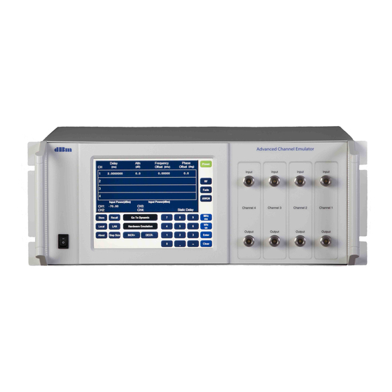
All local control is done via a touch sensitive graphics panel. Figure 1-1. Instrument Front Panel View Front view shows a four channel model. Multiple channel models have two Type N (f) connectors for each channel. For custom ACE9600 units, consult additional documentation provided with the instrument. ACE9600 Operations Manual... -
Page 13: Rear Panel Connections
BNC (f) connector, termination impedance: 50 ohms, AC coupled. Input level: sine, 0 dBm to + 3dBm (ACE9600 will automatically switch to its internal reference if no external reference is present) Update Clock input: (f) connector, termination impedance:130 ohms Thevenin equivalent to 1.3VDC, DC coupled. - Page 14 Advanced Channel Emulator MLVDS A/B: Proprietary interface for high speed interchange of data between up to four ACE chassis. USB: Factory use only ACE9600 Operations Manual...
-
Page 15: Start And Shutdown Procedures
Move the front panel power to the standby position. There may be a short delay before the instrument powers off. If the ACE9600 is going to be off for an extended period of time, you may wish to remove the main power by pressing the Line on/off switch on the rear of the instrument. - Page 16 Advanced Channel Emulator ACE9600 Operations Manual...
-
Page 17: Local Operation Overview
Local Operation Section Lo c a l Op e ra tio n Ove rvie w The ACE9600 is a laboratory instrument designed to apply impairments to an RF signal, simulating the effects that are encountered in a space based and/or terrestrial wireless channel. The link... -
Page 18: Operating States
Fwd key or Step Back key can be used to step through the parameter files at a definable time increment. Pressing the Start key from the PAUSED or READY state begins execution from the current point in the file. ACE9600 Operations Manual... -
Page 19: Front Panel Display Navigation:link Emulation
Advanced Channel Emulator Fro n t P a n e l Dis p la y Na vig a tio n :Lin k Em u la tio n Figure 2-1 illustrates the Static mode navigation keys found on all of the static mode displays. The Go To Dynamic (and conversely the Go To Static) mode key is used to switch between Static mode and Dynamic mode. -
Page 20: Navigation In Dynamic Mode
Anytime a parameter field is highlighted, that field can be edited. If another parameter key is pressed prior to pressing a units key, the highlight immediately moves to the appropriate field and the original parameter is not overwritten. Figure 2-2. Keypad ACE9600 Operations Manual... -
Page 21: Units Keys
3 possible units keys. The key assigns the order of magnitude to the data entered as follows: units Enter ms, Hz, degrees, dB, dBm, dBm/Hz, ratio us kHz us, kHz ms MHz... -
Page 22: To View The Instrument's Hardware Configuration
Store can be invoked from Static or Dynamic modes. Press a number from 1-8, designating a register to store the current instrument settings. Register 0 (labeled Preset State) defines the power up and Preset state. The register is overwritten. ACE9600 Operations Manual... -
Page 23: To Recall A Saved Instrument Setting
Advanced Channel Emulator Press Return to exit the store utility menu. Note: Register 9 is not available to store settings as this always contains the factory defaults. Figure 2-5. Store display To re c a ll a s a ve d in s tru m e n t s e ttin g Pressing the Recall key activates the Recall Settings display. -
Page 24: To Set The Instrument To Local Or Remote (Lan) Control
To p re s e t th e in s tru m e n t s ettin g s Pressing Preset causes the instrument to return to the default state which is defined by the contents of the Preset State register. ACE9600 Operations Manual... -
Page 25: Set Static Step Size (Delay, Attn, Freq Offset, Phase Offset, Rf, And Awgn, )
1 to 2999 MHz AWGN 0.1 to 60 dBm/Hz Ma x d ela y c h a n g e with s le win g e n a ble d A threshold value can be entered to define whether delay changes are implemented as a linear slew or as an instantaneous step. -
Page 26: Step + And Step - Keys
Step + and Step - keys change the parameter by its step size value. Figure 2-9 Static Delay display Figure 2-9 shows the front panel display in static mode. Each of 16 parameter fields can be edited by touching near the center of the value. ACE9600 Operations Manual... -
Page 27: Setting Delay Display Parameters
In p u t P owe r The rms input signal power is measured and displayed. The range of the measurement is 0 dBm to approximately -50 dBm. The displayed power is a true rms value, that is averaged over a period of approximately 1 second. -
Page 28: Setting Rf Menu Parameters
The ratio mode uses a true rms detector to measure the input signal power. Ratio and Bit Rate settings in combination with this measured power determine the applied noise density, such that the desired E ratio is achieved. The resultant noise density is displayed. ACE9600 Operations Manual... -
Page 29: Setting The Awgn Menu Parameters
=No + 10*Log(NBW), and NBW is the noise bandwidth.. With AWGN at full scale, the noise power is typically -16 dBm, and the maximum applied signal power must be 10.1 dBc below full scale at the instrument input. S e ttin g th e AWGN Me nu P a ra m e te rs... -
Page 30: Set Eb/No Ratio (Mode = E B N O )
In Static mode, the multipath display will appear as in the example figure below. Each of the Type, Doppler, Loss, and Delay parameters can be modified by pressing the touch sensitive display in the appropriate field. ACE9600 Operations Manual... -
Page 31: Setting The Multipath Fade Menu Parameters
When fading is enabled, the input signal must be limited to less than -6 dBm, and the resulting faded output signal power will be less than -19 dBm (dependent upon the path loss settings). -
Page 32: Multipath Submenu View
Rician K-factor, Angle of Arrival, path correlation and Log Normal controls. Any path can be correlated to any other path by a percentage ranging from 0%(totally uncorrelated) to 100% (fully correlated). Figure 2-13. Display for the Static Fading Submenu ACE9600 Operations Manual... -
Page 33: Soft Keys
Advanced Channel Emulator S o ft Ke ys CH: To view settings for other channels, press the CH key to cycle through all installed channels. The current channel number is displayed at bottom left of the display. Fading Disabled/Fading Enabled: Toggles between multipath fading active or bypassed Prev Menu: go to the main Fading view Paths 1-6 or Paths 7-12:Only six paths are displayed at a time. -
Page 34: Dynamic States
The instrument has finished execution of a single dynamic run. The last value of each parameter file is implemented in hardware. Dyn a m ic Mo d e Co n tro ls Figure 2-14. Dynamic Mode Control Keys ACE9600 Operations Manual... -
Page 35: Loop
Advanced Channel Emulator Lo o p Press the Loop key to toggle between “Single” and “Continuous”. In “Single”, parameter files are run from beginning to end, and then execution stops, and the mode changes to DONE. In “Continuous”, files are repeatedly run from beginning to end. Mode remains at RUN. Files can only be run in Continuous looping under the following conditions: the first data point and the last data point in the file are identical. -
Page 36: File Menu Key
Press the Timing Control key to invoke the Timing Control display. Dynamic parameters can be updated in several ways: Continuously at the selected update rate Continuously, but starting at a point in the data files other than the first point Single stepped forward or backward ACE9600 Operations Manual... -
Page 37: Continuous Dynamic Update
Advanced Channel Emulator Figure 2-15. Dynamic Timing Controls display Co n tin u o u s Dyn a m ic Up d a te There are three individual update rates. Each can be set on the respective parameter display or all three can be set on the Dynamic Timing Control display. -
Page 38: Dynamic File Start Point
A single trigger into the Master is distributed to the Slave units, to allow precise timing alignment with up to 16 channels. Figure 2-17. Multi-Chassis Sync Mode Keys ACE9600 Operations Manual... - Page 39 Advanced Channel Emulator The default setting is Standalone. The instrument will always power on and Preset to the Standalone mode. When multiple chassis are to be synchronized, one instrument must be set as Master, and the remaining instruments must be set as Slave(s). The external connections required to synchronize multiple chassis’...
-
Page 40: Dynamic File Menus
File Menu #1 allows the user to select files for 1) Delay 2) Attenuation 3) Frequency Offset and 4) Phase Offset. File Menu #2 allows the user to select files for 1) RF input frequency 2) RF output frequency 3) AWGN and 4) Multipath fading. Figure 2-20. File Menu #2 ACE9600 Operations Manual... -
Page 41: Scroll Down Key
Advanced Channel Emulator Each of the parameter fields indicates the currently selected dynamic data file name for that parameter. A selection of “None” will cause the parameter to remain at its current value. Characteristics of each file are displayed when the parameter is selected by touching the parameter field (the selected field is highlighted). - Page 42 10 nsec/msec 10 nsec/20msec 10.200110 100 nsec/msec 100 nsec/20msec 10.200010 100 nsec/msec 100 nsec/20msec AWGN dynamic files provide direct control of the noise density output power. Note that the ACE9600 does not calculate Eb/No ratio in dynamic mode. ACE9600 Operations Manual...
-
Page 43: Dynamic Rf Operation
Dyn a m ic RF Op e ra tion Figure 2-22. Dynamic RF display When the ACE9600 hardware is configured with internal L-band frequency converters, the RF input center frequency and RF output center frequency can be changed dynamically. The RF update rate must be equal or slower than the delay update rate. -
Page 44: Dynamic Data Files
<CR> separating the parameter fields. File names must begin with “DLY", “FRQ”, "ATN", "WGN", “RFF”, or “MPF” and have an extension of “.DAT” When the files are converted to a compressed format for the ACE9600, the ACE9600 Operations Manual... -
Page 45: Data File Description
Da ta File De s criptio n De la y File s The ACE9600 changes delay linearly over the update period. The delay change does not cause phase discontinuities. The change in delay between two adjacent data points must not require the delay to slew at a rate greater than 2 msec/sec, nor less than a rate of 0.5 psec/sec. -
Page 46: Attenuation Files
Frequency offset is typically used to impose the carrier Doppler shift that occurs as a result of time varying path length change. Note that dynamically changing delay in the ACE9600 causes a frequency shift proportional to the frequency offset from the instrument’s nominal center frequency. -
Page 47: Phase Offset Files
When noise density is enabled in static mode (either by direct entry or via Eb/No calculation), the noise will remain enabled at that level when the ACE9600 mode is changed to dynamic. If awgn is not desired in dynamic mode, it must be set to off in static mode. When a dynamic awgn file is loaded, awgn is automatically enabled, irrespective of whether it was on or off in static mode. -
Page 48: Multipath Fading Files
Kfactor dB 1 dB -10 to 20 dB Doppler Hz 1 Hz 0 to 10,000Hz Loss 0.1 dBm 0.0 to 30.0 dBm Delay usec 0.001 usec 0.000 to 9.996 usec degrees 1 degree 0 to 180 degrees RICE 1 20 0 0 10 RICE 12 30 10 10 20 ;0 0.000 0.0 0;;;;;;;;;;;11 0.011 1.1 11;... -
Page 49: Dynamic File Sizes
Each line in the file is ended with a carriage return. Spaces are allowable. Dyn a m ic File s ize s Parameter data file sizes are unlimited, however the total of all downloaded files is limited by the ACE9600 SD card memory capacity. ACE600 Operations Manual... -
Page 50: Remote Operation Overview
Remote Operation Section Re m o te Op e ra tio n Ove rview The ACE9600 can be controlled remotely using its LAN interface. The instrument can be connected to any IEEE-802 network. It uses TCP/IP, and achieves transfer rates up to 100 MSPS. The ACE is configured as a network server, and can communicate with a network client.
Need help?
Do you have a question about the ACE9600 and is the answer not in the manual?
Questions and answers