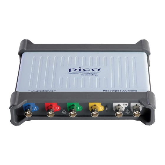
Summary of Contents for PICO PicoScope 5000 Series
- Page 1 PicoScope 5000 Series (A API) PC Oscilloscopes Programmer's Guide ps5000apg.en r2 Copyright © 2013-2015 Pico Technology Limited. All rights reserved.
-
Page 3: Table Of Contents
1 ps5000aBlockReady (callback) ............................27 2 ps5000aChangePowerSource ............................28 3 ps5000aCloseUnit ............................29 4 ps5000aCurrentPowerSource ............................30 5 ps5000aDataReady (callback) ............................31 6 ps5000aEnumerateUnits ............................32 7 ps5000aFlashLed ............................33 8 ps5000aGetAnalogueOffset ............................34 9 ps5000aGetChannelInformation ............................35 10 ps5000aGetDeviceResolution Copyright © 2013-2015 Pico Technology Limited. All rights reserved. ps5000apg.en r2... - Page 4 46 ps5000aSetEtsTimeBuffer ............................78 47 ps5000aSetEtsTimeBuffers ............................79 48 ps5000aSetNoOfCaptures ............................80 49 ps5000aSetPulseWidthQualifier ..................................82 1 ps5000a_PWQ_CONDITIONS structure ............................83 50 ps5000aSetSigGenArbitrary ..................................85 1 AWG index modes ............................87 51 ps5000aSetSigGenBuiltIn ............................90 52 ps5000aSetSigGenPropertiesArbitrary ps5000apg.en r2 Copyright © 2013-2015 Pico Technology Limited. All rights reserved.
- Page 5 ............................103 63 ps5000aStreamingReady (callback) 12 Programming examples ............................104 13 Driver status codes ............................105 14 Enumerated types and constants ............................110 15 Numeric data types ............................111 16 Glossary ............................112 ............................115 Index Copyright © 2013-2015 Pico Technology Limited. All rights reserved. ps5000apg.en r2...
-
Page 7: Introduction
PicoScope 5244B and deeper memory. PicoScope 5442B PicoScope 5443B PicoScope 5444B For information on any PicoScope 5000 Series oscilloscope, refer to the documentation on our website. Copyright © 2013-2015 Pico Technology Limited. All rights reserved. ps5000apg.en r2... -
Page 8: Minimum Pc Requirements
Introduction Minimum PC requirements To ensure that your PicoScope 5000 Series Oscilloscope operates correctly, you must have a computer with at least the minimum system requirements as shown in the following table. The performance of the oscilloscope will be better with a more powerful PC, and will benefit from a multi-core processor. -
Page 9: License Agreement
Access. The licensee agrees to allow access to this software only to persons who have been informed of and agree to abide by these conditions. Usage. The software in this release is for use only with Pico products or with data collected using Pico products. -
Page 10: Programming The 5000 Series Oscilloscopes
Programming the 5000 Series oscilloscopes dynamic link library in your PicoScope installation directory allows ps5000a.dll you to program a PicoScope 5000 Series (A API) oscilloscope using standard C function calls. A typical program for capturing data consists of the following steps: Open the scope unit. -
Page 11: The Ps5000A Driver
PicoIpp.dll, . These are installed by the SDK when you plug the oscilloscope into the WinUsb.sys computer for the first time. Your application does not call these drivers directly. Copyright © 2013-2015 Pico Technology Limited. All rights reserved. ps5000apg.en r2... -
Page 12: System Requirements
USB 1.1, USB 2.0, and USB 3.0 connections. The 5000 A and B Series oscilloscopes are all hi-speed USB 2.0 devices, so transfer rate will not increase by using USB 3.0, but it will decrease when using USB 1.1. ps5000apg.en r2 Copyright © 2013-2015 Pico Technology Limited. All rights reserved. -
Page 13: Voltage Ranges
–32 767 8001 zero 0000 ps5000aMaximumValue maximum +32 767 7FFF You can determine the minimum and maximum scaled values for the currently selected resolution using the ps5000aMinimumValue ps5000aMaximumValue function calls. Copyright © 2013-2015 Pico Technology Limited. All rights reserved. ps5000apg.en r2... -
Page 14: Triggering
Triggering Triggering PicoScope 5000 Series oscilloscopes can either start collecting data immediately, or be programmed to wait for a trigger event to occur. In both cases you need to use the PicoScope 5000 trigger function which in turn calls ps5000aSetSimpleTrigger,... -
Page 15: Sampling Modes
PicoScope 5000 Series (A API) Programmer's Guide Sampling modes PicoScope 5000 Series oscilloscopes can run in various sampling modes. Block mode. In this mode, the scope stores data in its buffer memory and then transfers it to the PC. When the data has been collected it is possible to examine the data, with an optional downsampling factor. -
Page 16: Block Mode
Sampling modes Block mode In block mode, the computer prompts a PicoScope 5000 Series oscilloscope to collect a block of data into its internal memory. When the oscilloscope has collected the whole block, it signals that it is ready and then transfers the whole block to the computer's memory through the USB port. -
Page 17: Using Block Mode
USB 2.0 connection. To avoid hanging the calling thread, it is possible to call ps5000aGetValuesAsync instead. This immediately returns control to the calling thread, which then has the option of waiting for the data or calling ps5000aStop abort the operation. Copyright © 2013-2015 Pico Technology Limited. All rights reserved. ps5000apg.en r2... -
Page 18: Rapid Block Mode
In normal block mode, the PicoScope 5000 series scopes collect one waveform at a time. You start the the device running, wait until all samples are collected by the device, and then download the data to the PC or start another run. There is a time overhead of tens of milliseconds associated with starting a run, causing a gap between waveforms. - Page 19 Call ps5000aGetValuesBulk for each pair of buffers. 10a. Retrieve the time offset for each data segment using ps5000aGetValuesTriggerTimeOffsetBulk64. Continue from step 11 above. Copyright © 2013-2015 Pico Technology Limited. All rights reserved. ps5000apg.en r2...
-
Page 20: Rapid Block Mode Example 1: No Aggregation
1000 samples as defined by MAX_SAMPLES. There are only 10 buffers set, but it is possible to set up to the number of captures you have requested. can be substituted for PS5000A_RATIO_MODE_AGGREGATE, PS5000A_RATIO_MODE_NONE PS5000A_RATIO_MODE_DECIMATE, or PS5000A_RATIO_MODE_AVERAGE. ps5000apg.en r2 Copyright © 2013-2015 Pico Technology Limited. All rights reserved.


Need help?
Do you have a question about the PicoScope 5000 Series and is the answer not in the manual?
Questions and answers