
Related Manuals for PICO PicoScope 5000 A


Summary of Contents for PICO PicoScope 5000 A
- Page 1 PicoScope 5000 A and B ® Flexible Resolution Oscilloscopes User's Guide ps5000ab.en r5...
-
Page 2: Table Of Contents
5 Product information ......................10 1 Model comparison tables ........................10 2 Connector diagrams ..........................11 3 Connector information ......................... 12 4 Probe compensation ..........................13 6 Glossary ..........................14 Index ............................. 16 ps5000ab.en r5 Copyright © 2013–2017 Pico Technology Limited. All rights reserved. -
Page 3: Welcome
PicoScope 5442B PicoScope 5443B PicoScope 5444B Here are some of the benefits provided by the PicoScope 5000 A and B Series oscilloscopes: · Programmability: The PicoScope 5000A SDK lets you write your own programs, in your chosen programming language, to control all the features of the scope. Using the API functions, you can develop your own programs to collect and analyze data from the oscilloscope. -
Page 4: Introduction
Appearance on the product indicates a need to Caution read this Safety and operation instruction. Static awareness. Static discharge can damage part(s). IEC 61010 overvoltage category Do not dispose of this product as unsorted municipal waste ps5000ab.en r5 Copyright © 2013–2017 Pico Technology Limited. All rights reserved. -
Page 5: Product Usage
PicoScope 5000 A and B Series Flexible Resolution Oscilloscopes User's Guide 2.1.2 Product usage WARNING To prevent injury or death, use the product only as instructed and use only accessories supplied or recommended. Protection provided by the product may be impaired if used in a manner not specified by the manufacturer. -
Page 6: Grounding
Take care to avoid mechanical stress or tight bend radii for all connected leads, including all coaxial leads and connectors. Mishandling will cause deformation of sidewalls, and will degrade performance and measurement accuracy. ps5000ab.en r5 Copyright © 2013–2017 Pico Technology Limited. All rights reserved. -
Page 7: Environment
The product contains no user-serviceable parts. Repair, servicing and calibration require specialized test equipment and must only be performed by Pico Technology or an approved service provider. There may be a charge for these services unless covered by the Pico five year warranty. -
Page 8: Conformance
Copyright. Pico claims the copyright of and reserves the rights to all material (software, documents etc) contained in this release. Liability. Pico and its agents shall not be liable for any loss or damage, howsoever caused, related to the use of Pico equipment or software, unless excluded by statute. -
Page 9: Trademarks
Goods will be free from defects in material and workmanship. Pico Technology shall not be liable for a breach of the warranty if the defect has been caused by fair wear and tear, willful damage, negligence, abnormal working conditions or failure to follow Pico Technology's spoken or written advice on the storage, installation, commissioning, use or maintenance of the Goods or (if no advice has been given) good trade practice;... -
Page 10: Pack Contents
Pack contents Pack contents A PicoScope 5000 A or B Series oscilloscope is supplied with the following items: · Standard USB cable (4-channel scopes only) · Double-headed USB cable · AC adaptor (4-channel scopes only) · Software and Reference CD ·... -
Page 11: Installation
PicoScope 5000 A and B Series Flexible Resolution Oscilloscopes User's Guide Installation Please note the various power supply options below. Full instructions are in the Quick Start Guide supplied with your oscilloscope. Powering 2-channel scopes Connect your PicoScope 5000 Series 2-channel oscilloscope to two free, powered USB ports on the PC or USB hub using the double-headed USB cable supplied (see image 1 below). -
Page 12: Product Information
250 MS/s 250 MS/s 12-bit 500 MS/s 250 MS/s 125 MS/s 125 MS/s 14-bit 125 MS/s 125 MS/s 125 MS/s 125 MS/s 15-bit 125 MS/s 125 MS/s 16-bit 62.5 MS/s ps5000ab.en r5 Copyright © 2013–2017 Pico Technology Limited. All rights reserved. -
Page 13: Connector Diagrams
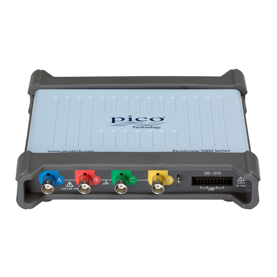
PicoScope 5000 A and B Series Flexible Resolution Oscilloscopes User's Guide Connector diagrams PicoScope 5000 A and B Series oscilloscopes A. Input channel A B. Input channel B C. Input channel C D. Input channel D Probe compensation output 2. LED: red when scope is connected but not operating. Flashes green when the oscilloscope is capturing data. -
Page 14: Connector Information
10:1 and switched 1:1/10:1 types. The probes supplied with the PicoScope 5000 A and B Series oscilloscopes have been trimmed specifically for use with the scopes they are supplied with. For optimum performance, please use the probes supplied. -
Page 15: Probe Compensation
PicoScope 5000 A and B Series Flexible Resolution Oscilloscopes User's Guide Probe compensation We recommend that you compensate each oscilloscope probe before using it with your PicoScope. Compensation instructions specific to the probe are included in the leaflet supplied with the probe. -
Page 16: Glossary
In this mode you can measure the peak-to-peak amplitude of an AC signal but not its absolute value. Use the DC setting for measuring the absolute value of a signal. Driver. A program that controls a piece of hardware. The driver for the PicoScope 5000 A and B Series ps5000a. - Page 17 PicoScope 5000 A and B Series Flexible Resolution Oscilloscopes User's Guide Signal generator. A built-in circuit that generates signals suitable for driving an external device under test. Its output is the BNC connector marked Gen on the oscilloscope. See also Connector information.
-
Page 18: Index
Glossary 14 Trademarks 7 Ground terminal 11 USB 4, 9, 15 Input channel 11, 12 double-headed cable 4, 9 Input range 14 port 11 Installation 9 single-headed cable 4, 9 ps5000ab.en r5 Copyright © 2013–2017 Pico Technology Limited. All rights reserved. - Page 19 PicoScope 5000 A and B Series Flexible Resolution Oscilloscopes User's Guide Vertical resolution 15 Voltage range 14 Warranty 7 Copyright © 2013–2017 Pico Technology Limited. All rights reserved. ps5000ab.en r5...
- Page 20 Tel: +44 (0) 1480 396 395 Tel: +1 800 591 2796 Tel: +86 21 2226-5152 Fax: +44 (0) 1480 396 296 Fax: +1 620 272 0981 sales@picotech.com pico.china@picotech.com support@picotech.com www.picotech.com ps5000ab.en r5 2017-09-04 Copyright © 2013–2017 Pico Technology Limited. All rights reserved.
Need help?
Do you have a question about the PicoScope 5000 A and is the answer not in the manual?
Questions and answers