Table of Contents
Advertisement
Quick Links
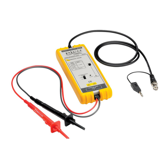
25 MHz ±700 V Differential Probe
This probe complies with IEC-1010.1, IEC-1010.2-031 CAT III,
Pollution Degree 2.
1. Safety terms and symbols
Terms appearing in this manual:
Symbols appearing on the product:
Danger
High Voltage
DO141-4
TA041
User's Manual
WARNING
Warning statements identify conditions or practices
that could result in injury or death.
CAUTION
Caution statements identify conditions or practices
that could result in damage to this product or other
property.
(Earth) Terminal
Protective
Attention
Refer to Manual
Advertisement
Table of Contents

Subscribe to Our Youtube Channel
Related Manuals for PICO TA041


Summary of Contents for PICO TA041
-
Page 1: Safety Terms And Symbols
TA041 25 MHz ±700 V Differential Probe User’s Manual This probe complies with IEC-1010.1, IEC-1010.2-031 CAT III, Pollution Degree 2. 1. Safety terms and symbols Terms appearing in this manual: WARNING Warning statements identify conditions or practices that could result in injury or death. -
Page 2: General Safety Summary
To avoid electric shock, do not operate this probe in wet or damp conditions. Do not operate in explosive atmosphere To avoid injury or fire hazard, do not operate this probe in an explosive atmosphere. © Copyright Pico Technology 2008–2012 DO141-4... -
Page 3: Installation
CAUTION This probe is designed for carrying out differential measurements between two points on the circuit under test. It is not intended for electrically insulating the circuit under test and the measuring instrument. DO141-4 © Copyright Pico Technology 2008–2012... -
Page 4: Power Leads
Two types of power leads are available for use with this instrument: ® ® Lemo Lead: For oscilloscopes with Lemo power connectors. ® ® Probus Lead: For oscilloscopes with Probus power connectors. Oscilloscope front panel © Copyright Pico Technology 2008–2012 DO141-4... -
Page 5: Specifications
If the polarity is wrong, a built-in circuit protects the probe so that no danger or damage will occur. When the voltage of the cells becomes too low, the power indicator on the panel will flicker. DO141-4 © Copyright Pico Technology 2008–2012... -
Page 6: Derating Curve
TA041 User’s Manual Pico Technology 8. Derating curve The derating curve for absolute maximum input voltage is as follows: 10000 1000 1000 1000 1.E+06 1.E+07 1.E+08 10 M 100 M Frequency (Hz) © Copyright Pico Technology 2008–2012 DO141-4... -
Page 7: Test Procedure
This means the probe is working properly. 10. Calibrating the unit There are three main sources of uncertainty when calibrating a Pico differential probe in addition to any uncertainty in the test setup. These are: The stated DC accuracy of the probe under test (±2%). - Page 8 Added calibration notes. Pico Technology James House Colmworth Business Park St. Neots Cambridgeshire PE19 8YP United Kingdom www.picotech.com ® ® Lemo , Probus and Pico Technology are registered trademarks. Manufactured in Republic of China. © Copyright Pico Technology 2008–2012 DO141-4...
Need help?
Do you have a question about the TA041 and is the answer not in the manual?
Questions and answers