Summary of Contents for PICO 2000 Series
- Page 1 PicoScope 2000 Series PC Oscilloscopes User's Guide PS2000044-1.1 Copyright 2005-6 Pico Technology Limited. All rights reserved.
-
Page 2: Table Of Contents
PicoScope 2000 Series User Guide Table of Contents 1 Introduction ...1 1 Overview 2 Safety symbols 3 Safety warning 4 FCC notice 5 CE notice 6 Licence conditions 7 Trademarks 8 Warranty 9 Company details ...5 2 Product information 1 Minimum system requirements... -
Page 3: Introduction
USB 2.0 capable and backwards compatible with USB 1.1. There is no need for an additional power supply as power input is from the USB port, so these oscilloscopes are highly portable. With the PicoScope software , you can use PicoScope 2000 series oscilloscopes as PC Oscilloscopes and spectrum analysers; with the data loggers. -
Page 4: Safety Warning
Maximum input range PicoScope 2000 Series PC Oscilloscopes are designed to measure voltages in the range -20 V to +20 V. Any voltages in excess of ±100 V may cause physical damage. -
Page 5: Ce Notice
CE notice The PicoScope 2000 Series of PC Oscilloscopes meets the intent of the 89/336/EEC and has been designed to Immunity standard. Products from the PicoScope 2000 series also meet the intent of the Directive and have been designed to meet the (safety requirements for electrical equipment, control, and laboratory use) standard. -
Page 6: Warranty
PicoScope 2000 Series User Guide Warranty Pico Technology warrants upon delivery, and for a period of 24 months unless otherwise stated from the date of delivery, that the Goods will be free from defects in material and workmanship. Pico Technology shall not be liable for a breach of the warranty if the defect has been... -
Page 7: Product Information
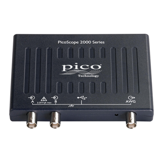
Disk space Operating system Ports Installation instructions Do not connect a PicoScope 2000 series PC Oscilloscope to the PC until you have installed the software. Install the software by following the steps in the installation guide supplied with your oscilloscope. - Page 8 PicoScope 2000 Series User Guide input impedance is also standard, so the x10 function on scope probes works correctly. Connector diagram USB port connector. LED. When lit, indicates the oscilloscope is sampling data. Channel A input. Channel B input. PS2000044-1.1...
-
Page 9: Specifications
Compliance Sampling modes PicoScope 2000 series PC Oscilloscopes can run in various sampling modes. At high sampling rates, the oscilloscope collects data much faster than a PC can read it. To compensate for this, the oscilloscope stores a block of data in an internal memory buffer, delaying transfer to the PC until a preset number of data points has been sampled. -
Page 10: Glossary
A software application that controls a piece of hardware. The driver for the 2000 series PC Oscilloscopes is supplied in the form of a 32 bit Windows DLL. This is used by the PicoScope and PicoLog software to control the oscilloscopes. -
Page 11: Vertical Resolution
Glossary oscilloscope, spectrum analyser, and meter display. Real time continuous mode A sampling mode in which the software repeatedly requests single samples from the oscilloscope. This mode is suitable for low sampling rates when you require the latest sample to be displayed as soon as it is captured. Streaming mode A sampling mode in which the oscilloscope samples data and returns it to the computer in an unbroken stream. -
Page 12: Index
PicoScope 2000 Series User Guide Index Accuracy Analog bandwidth BNC connector Buffer size Calibration Contact details Data logger Dimensions Humidity Input range (maximum) Inputs Maximum input range Operating environment Oscilloscope probe Overload protection PC connection PC oscilloscopes 1, 3 PicoLog software PS2000044-1.1... - Page 13 Pico Technology Ltd The Mill House Cambridge Street St Neots PE19 1QB United Kingdom Tel: +44 (0) 1480 396 395 Fax: +44 (0) 1480 396 296 Web: www.picotech.com PS2000044-1.1 4.12.07 Copyright 2005-6 Pico Technology Limited. All rights reserved.


Need help?
Do you have a question about the 2000 Series and is the answer not in the manual?
Questions and answers