Table of Contents
Advertisement
Advertisement
Table of Contents

Related Manuals for PICO TA467


Summary of Contents for PICO TA467
- Page 1 TA467 Insulation tester User’s guide www.picoauto.com...
-
Page 2: Table Of Contents
4.14. SETUP (SET) ........................... 19 4.15. AC + DC ........................... 19 4.16. Low battery indication ......................19 4.17. Maintenance ........................... 20 4.17.1. Battery installation ........................20 4.18. Technical specifications ......................21 Copyright © 2020 Pico Technology Ltd. All rights reserved. DO341-1... -
Page 3: Description
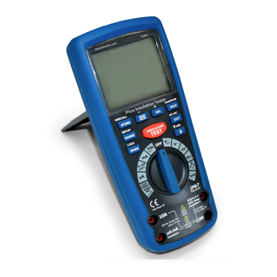
TA467 Insulation Tester User’s Guide 1. Description The TA467 Insulation tester is specially designed for vehicles with on-board high voltagesand conforms to EN61010 CAT III (1000 volts) and CAT IV (600 volts). The insulation test function allows testing of the insulation of the high voltage wires found on high-voltage vehicles. It can be used as a stand-alone device or linked wirelessly with a USB interface to a PC or laptop so you can have the results graphed, saved or printed. -
Page 4: Symbols And Annunciators
Peak hold Ω Ohms Volts Hertz (frequency) Relative Percent (duty ratio) AUTO Autoranging Alternating current HOLD Display hold Direct current °C Degrees Celsius °F Degrees Fahrenheit Minimum Maximum RF icon Copyright © 2020 Pico Technology Ltd. All rights reserved. DO341-1... -
Page 5: Operating Instructions
3. Touch the black test probe tip to the negative side of the circuit and touch the red test probe tip to the positive side of the circuit. 4. Read the voltage in the display. DO341-1 Copyright © 2020 Pico Technology Ltd. All rights reserved. -
Page 6: Ac Voltage Measurements (Frequency, Duty Cycle)
7. Press the MODE again to read the % of duty cycle in the main display. 8. Press EXIT 9. Press and hold the AC + DC button for two seconds to switch to AC + DC. 10. Test AC and DC TRUE RMS. Copyright © 2020 Pico Technology Ltd. All rights reserved. DO341-1... -
Page 7: Mv Voltage Measurements
3. Touch the test probe tips to the circuit or part you wish to check. It is best to disconnect one side of the part you are testing to avoid interference from both sides of the circuit. 4. Read the resistance in the display. DO341-1 Copyright © 2020 Pico Technology Ltd. All rights reserved. -
Page 8: Dc Current Measurements
6. Touch the black test probe tip to the negative side of the circuit and touch the red test probe tip to the positive side of the circuit. 7. Apply power to the circuit. 8. Read the current in the display. Copyright © 2020 Pico Technology Ltd. All rights reserved. DO341-1... -
Page 9: Ac Current Measurements (Frequency, Duty Cycle)
14. Press the MODE button to select AC. 15. Press and hold the AC + DC button for two seconds to switch to AC + DC. 16. Test AC and DC TRUE RMS. DO341-1 Copyright © 2020 Pico Technology Ltd. All rights reserved. -
Page 10: Continuity Check
V on the display. 4. Touch the test probes to the circuit on either side of the diode under test. Forward voltage will typically indicate 0.400 to 0.700 V. Reverse voltage will indicate OL. Shorted devices will indicate near 0 V and open devices will indicate OL in both polarities. Copyright © 2020 Pico Technology Ltd. All rights reserved. DO341-1... -
Page 11: Capacitance Measurements
Note: The temperature probe is fitted with a K-Type mini connector. The tool is supplied with a mini to banana adaptor to connect to the input jacks on the unit. DO341-1 Copyright © 2020 Pico Technology Ltd. All rights reserved. -
Page 12: Frequency (Duty Cycle) Measurements (Electronic)
7. Apply power to the circuit. 8. The loop current will be displayed as a % with 0 mA=-25%, 4 mA=0%, 20 mA=100% and 24 mA=125%. Copyright © 2020 Pico Technology Ltd. All rights reserved. DO341-1... -
Page 13: Insulation Resistance Measurements
iv. The insulation resistance and achieved test voltage will continue to be displayed for approximately 20 seconds, although you can push and release the EXIT button within this period to clear the display and discharge any residual test voltage from the tester. DO341-1 Copyright © 2020 Pico Technology Ltd. All rights reserved. - Page 14 5. Rotate the function switch to OFF to exit the test. This discharges any remaining insulation test voltage through an internal switch, which will take approximately two seconds. Copyright © 2020 Pico Technology Ltd. All rights reserved. DO341-1...
- Page 15 Check the insulation resistance between conductors by connecting the test leads to conductors in pairs. DO341-1 Copyright © 2020 Pico Technology Ltd. All rights reserved.
-
Page 16: Auto-Ranging/Manual Range Selection
The backlight will automatically turn off after the set time (see page 19 to learn how to change this setting). Press the button to exit the backlight-on mode. Copyright © 2020 Pico Technology Ltd. All rights reserved. DO341-1... -
Page 17: Hold
Note: The time display is limited to four digits. To exit the STORE function, press the EXIT button. DO341-1 Copyright © 2020 Pico Technology Ltd. All rights reserved. -
Page 18: Data Storage Recall
Note: The time stamp for the transferred data is the time it was transferred, not captured. Note: Refer to the HELP file included in the software for in-depth software instructions. Copyright © 2020 Pico Technology Ltd. All rights reserved. DO341-1... -
Page 19: Setup (Set)
AC measurement. The display will show the AC+DC icon. Press the EXIT button to exit the mode. Low battery indication 4.16. When the icon appears alone in the display, you need to replace the battery. DO341-1 Copyright © 2020 Pico Technology Ltd. All rights reserved. -
Page 20: Maintenance
7. Put the rear cover, batteries and battery cover back in place and secure with the designated screws. Make sure you do not trap the supply wires when you put the rear cover back on. Copyright © 2020 Pico Technology Ltd. All rights reserved. DO341-1... -
Page 21: Technical Specifications
400 mA 0.1 mA 10 A 0.01 A (20 A: 30 seconds max with reduced accuracy) All AC current ranges are specified from 5% of range to 100% of range. DO341-1 Copyright © 2020 Pico Technology Ltd. All rights reserved. - Page 22 ± (1.0% reading + 4.5 °F) 4-20 mA% -25 to 125% 0.1 °F ± 50 digits 0 mA = -25%, 4 mA = 0%, 20 mA = 100%, 24 mA = 125% Copyright © 2020 Pico Technology Ltd. All rights reserved. DO341-1...
- Page 23 1 mA @ load ≤ 1 mA (0% ~ +10%) 4.000 MΩ 1 MΩ 4.001 ~ 0.01 MΩ ±(2% + 10) 40.00 MΩ 40.01 ~ 0.1 MΩ ±(2% + 5) 400.0 MΩ 400.1 ~ 1 MΩ ±(4% + 5) 4000 MΩ DO341-1 Copyright © 2020 Pico Technology Ltd. All rights reserved.
- Page 24 Cambridgeshire United States PE19 8YP United Kingdom Tel: +44 (0) 1480 396395 Tel: +1 800 591 2796 Tel: +49 (0) 5131 907 6290 Email: support@picotech.com Email: support@picotech.com Email: info.de@picotech.com www.picoauto.com Copyright © 2020 Pico Technology Ltd. All rights reserved. DO341-1...
Need help?
Do you have a question about the TA467 and is the answer not in the manual?
Questions and answers