Table of Contents
Advertisement
Quick Links
PLEASE READ CAREFULLY AND KEEP
THIS MANUAL FOR FUTURE REFERENCE
Instruction Manual
YOU CAN CONSULT A PROFESSIONNAL INSTALLER OR ASK FIRE OFFICIALS OR LOCAL AUTORITY ABOUT
RESTRICTION AND INSTALLATION INSPECTION IN YOUR AREA.
ULTIMATE TOR
Certified and tested according to
CAN
/ULC S627
CSA B415.1
490, rue de l'Argon
Québec, CANADA G2N 2C9
Tél.: 418-849-8095
Fax : 418-849-0077
www.jaroby.com
PR_I020/2023-08-11-EN
Revision: 5
Printed in Canada
Advertisement
Table of Contents

Related Manuals for J. A. Roby ULTIMATE TOR 2015


Summary of Contents for J. A. Roby ULTIMATE TOR 2015
- Page 1 PLEASE READ CAREFULLY AND KEEP THIS MANUAL FOR FUTURE REFERENCE Instruction Manual YOU CAN CONSULT A PROFESSIONNAL INSTALLER OR ASK FIRE OFFICIALS OR LOCAL AUTORITY ABOUT RESTRICTION AND INSTALLATION INSPECTION IN YOUR AREA. ULTIMATE TOR Certified and tested according to /ULC S627 CSA B415.1 490, rue de l'Argon...
-
Page 2: Table Of Contents
Stainless steel tubes replacement ..........21 Adjustment of the fan speed ............32 Stainless steel tube Installation ..........21 J. A. Roby Limited Lifetime warranty ..........33 Tube support installation ............... 22 Operating Instructions ..............23 Removable Handle Installation ............. 23... -
Page 3: Introduction
Introduction Warning Save these instructions. This manual describes the operation and installation of J.A. Roby woodstove model: Ultimate Tor. This appliance responds to CSA B415.1 with -DO NOT USE CHEMICALS OR FLUIDS TO START THE sized controlled cord wood. The capacity of this appliance is FIRE from 16 650 BTU/h to 59 262 BTU/h. -
Page 4: Rating Plate
Rating plate PR_I020/2023-08-11-EN Revision: 5... -
Page 5: Appliance Dimension
Appliance Dimension PR_I020/2023-08-11-EN Revision: 5... -
Page 6: Specifications
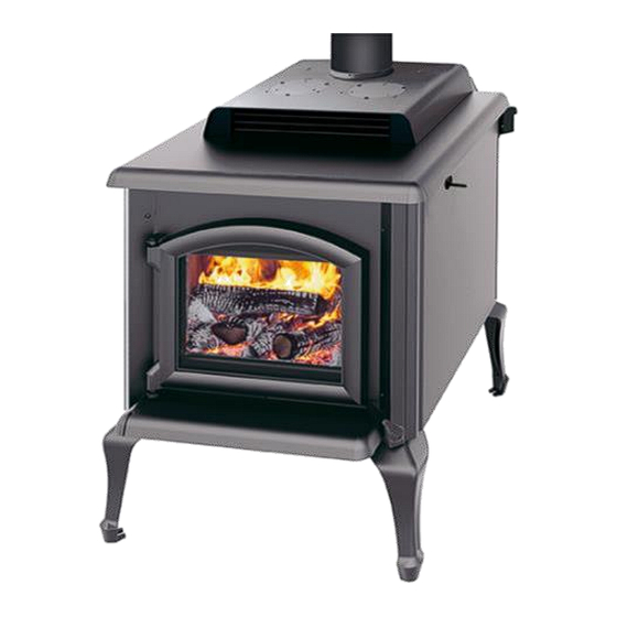
Specifications Ultimate Tor 2015 Combustible Wood Recommended surface 3800 ft² area Capacity 120 000 BTU/h Flue pipe diameter 6 in (15.4 cm) Minimal chimney height 12 ft. (365 cm) Exterior Height 37 13/16 in (96 cm) Exterior Width 29 in (73.6 cm) -
Page 7: Installation
Installation If this room heater is not properly installed, a house fire may Floor protection plate minimum result. To reduce the risk of fire, follow the installation dimensions instructions. Contact local building or fire officials about restrictions and installation inspection requirements in your The following dimensions are the minimums values and they area. -
Page 8: Minimums Clearances To Combustible Material
Minimums clearances to combustible material This appliance needs a minimum space because of these reduced clearances. Whether in the living room or the dining Regarding reducing that dimension, you must room, the stove will match perfectly by its originality and contact your local authority to know how to install heating. -
Page 9: Assembly Before Installation
Assembly before installation Fan and Snap disc box installation The stove leg might not be assembled in the factory, in order to save space for transportation and storage. You must therefore assemble these parts before installing the stove. DO NOT USE THE APPLIANCE WITHOUT INSTALLING THE LEGS. -
Page 10: Firebricks Installation
Firebricks installation Back firebricks installation Bottom firebricks installation Put 4 bricks «A» and «C» against the back wall. Put 4 bricks «A» in the bottom as shown in the picture below. After, insert 5 bricks «A» in front of the 4 bricks previously placed. -
Page 11: Side Firebricks Installation
Side firebricks installation Repeat steps1 2 and 3 to do the other side of the stove. Put 3 bricks «A» and 1 angled brick «T» beside the right air passage. Firebricks installation on the pipes The firebricks must be put on the 5 pipes from the back of the combustion chamber. - Page 12 Before to put the 4 bricks « A » over the 3 front pipes as Put two half metal discs over the rockwool near the rear shown in the illustration, insert the rockwool on the 4 bricks deflector already in place. Be sure to put it under the rear previously put on the tube.
-
Page 13: Firebox Configuration And Part List
Firebox configuration and part list PR_I020/2023-08-11-EN Revision: 5... -
Page 14: General Stove Installation Steps
General stove installation steps Note: This appliance has to be connected to 6 inches (15.24 cm) factory build chimney HT UL 103 or CAN/ULC S629 compliant or a 6 inches (15.24 cm) masonry chimney Location considerations with a homologated sleeve inside. Do not install the chimney directly at the outlet of the appliance. -
Page 15: Chimney Connector Installation
Chimney connector installation For direct vertical installation you will need: The chimney connector is a set of single wall or double wall ▪ 1 adequate length of vertical section; flue pipes and elbow installed between the stove collar and the ▪... -
Page 16: General Steps Of Chimney Installation
recommended by the manufacturer of your chimney. General steps of chimney installation Install fireguard in each level. Use only approved chimneys of the same size as the output of Frame the hole into the roof. the appliance, which means 6 inches in the case of this stove. The chimneys must be tested according to CAN/ULC-S629- Install a chimney support and a fireguard in the ceiling M87 in Canada and to UL-103 (type HT) The appliance can be... -
Page 17: Inside Masonry Chimney, Vertical Installation
Inside Masonry Chimney, Vertical Outside Vertical Installation Installation The wood burning appliance must be installed in accordance with the applicable local laws or the CAN/CSA-B365. Follow The wood burning appliance must be installed in accordance the chimney manufacturer’s instructions for installation. with the applicable local laws or the CAN/CSA-B365, Follow the chimney manufacturer’s instructions to install the chimney. -
Page 18: Cathedral Vertical Installation
Cathedral Vertical Installation Offset Installation The wood burning appliance must be installed in accordance The wood burning appliance must be installed in accordance with the applicable local laws or the CAN/CSA-B365. Follow with the applicable local laws or the CAN/CSA-B365. Follow the chimney manufacturer’s instructions to install the chimney. -
Page 19: Vertical Installation
Do not fill the gap between the framing and the chimney. Vertical Installation Nothing must be in contact with the chimney. The wood burning appliance must be installed in accordance Always install a fire-wall at each level, in a wall, a ceiling, a floor with the applicable local laws or the CAN/CSA-B365. -
Page 20: External Combustion Air Source
External combustion air source In conventional designed homes, natural ventilation is enough to operate the wood stove efficiently. In Novoclimat homes, stoves might not work properly. When some appliances are in motion, such as tumble dryer, kitchen hood or bathroom fan, the smoke might come in the house because of the depressurization which they would cause. -
Page 21: Part Replacement
Stainless steel tubes replacement Part replacement Although the tubes are in stainless steel, they will be eventually corroded and perforated by the extreme temperature and Steel deflector replacement conditions. They must be replaced by a new one to ensure performance of your stove. Internal steel deflectors are used in the combustion chamber Stainless steel tube Installation to protect the steel deflector placed underneath from the... -
Page 22: Tube Support Installation
Tube support installation Put the support over the tube and fix it at the top of the combustion chamber with the screws as shown. PR_I020/2023-08-11-EN Revision: 5... -
Page 23: Operating Instructions
Lightning fire Operating Instructions After installing correctly the stove following the installation instruction of the manufacturer, you are ready to light it. ➢ OPERATE ONLY WHEN DOOR IS CLOSED: Keeping the Turn the admission handle in horizontal position to set door open might over fire and cause permanent the primary air admission. -
Page 24: Keep A Fire
Even if this nuisance is temporary, open the windows and the In most parts in the North America, the minimum moisture doors in order to ensure a good ventilation. This special paint content that can be generally obtained in air drying is about 12 is conceived to tolerate temperatures until 1200°F (650°C). -
Page 25: Maintenance
Maintenance The chimney and the chimney connector must be inspected at Ash Removal least one every two months during the warming season or more depending on your installation. You can call a Chimney The wood burning make some residual called ash and it must sweeper to evaluate the creosote formation or you can do it be removed from the combustion chamber to help oxygen yourself - extinguish the wood stove and wait until it cools... -
Page 26: Door Maintenance
Door maintenance Disassembly and reassembly of door Do not unscrew the lower hinge when disassemble the door. The door is the mobile element that needs a special attention. Its tightness is very important. If you see the white soot sticking Keep the door locked. -
Page 27: Replacing Glass Fiber Rope
What to do in case of Chimney Replacing glass fiber rope Fire When the braided glass fibre rope is all flattened out, it becomes impossible to close the door hermetically. This means that the glass fibre rope is no longer usable or that the Contact your local authority to know what to do in case of rope is damaged. -
Page 28: Annex 1
Annex 1 Door assembly Square Door Arc Door PR_I020/2023-08-11-EN Revision: 5... -
Page 29: Annex 2
Annex 2 Circuit diagram of fan Snap Disc Box parts description PR_I020/2023-08-11-EN Revision: 5... -
Page 30: Annex 3
Annex 3 Parts that can be replaced • Bricks • Stove ceramic glass Arc • Stove ceramic glass Rectangular • Spring Handle • Stove Door with handle • Fans • Flat fiberglass rope (around glass) • Round fiberglass rope • Slotted Brick Washer To ordered parts call your stove seller representative. -
Page 31: Annex 4
Annex 4 Installation of optional fan kits 460 CFMs fan kit (part #: VENT460 TH) Step 1 : Remove the access panel (B) on the back of the appliance by unscrewing / untightening the 3 screws (A). Insert the 4 bolts (C) inside the fan housing at the designated location by passing the hand through the access opening. -
Page 32: Installation Of The Optional 460 Cfms Second Blower (Part #: Vent460T+)
Installation of the optional 460 CFMs second blower (part #: VENT460T+) Step 1 : Remove the bottom right plate. Push on one side of the plate to tilt it. Keep twisting the plate until it comes apart. Step 2 : If it’s not already done, remove the access panel (B) on the back of the appliance by unscrewing / untightening the 3... -
Page 33: J. A. Roby Limited Lifetime Warranty
WOOD BURNING STOVES & FIREPLACES J. A. ROBY’s warranty only applies to original buyer and is non-transferable. This warranty covers brand new products only, which have not been altered, modified or repaired since shipment from factory. The products covered by this warranty must be manufactured after review date indicated at the bottom of page.
Need help?
Do you have a question about the ULTIMATE TOR 2015 and is the answer not in the manual?
Questions and answers