Table of Contents
Advertisement
Quick Links
CONTACT LOCAL BUILDING OR FIRE OFFICIALS ABOUT RESTRICTIONS AND INSTALLATION INSPECTION REQUIREMENTS IN THE
AREA.
READ THIS ENTIRE MANUAL BEFORE INSTALLATION AND USE OF THIS WOOD INSERT. FAILURE TO FOLLOW THESE
INSTRUCTIONS COULD RESULT IN PROPERTY DAMAGE, BODILY INJURY OR EVEN DEATH.
READ AND KEEP THIS MANUAL FOR REFERENCE
Printed in Canada
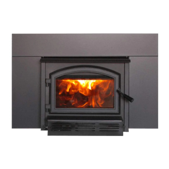
ARCHWAY 1700
INSERT
(Model WB17IN)
Installation
and Operation
Manual
Safety tested according to
ULC S628, UL 1482 and
UL 737 by an accredited
US Environmental Protection
Agency phase II certified
2020 cord wood insert.
laboratory.
2019-05-22
Advertisement
Table of Contents

Related Manuals for Empire Comfort Systems WB17IN


Summary of Contents for Empire Comfort Systems WB17IN
- Page 1 Installation and Operation Manual ARCHWAY 1700 INSERT (Model WB17IN) Safety tested according to ULC S628, UL 1482 and UL 737 by an accredited laboratory. US Environmental Protection Agency phase II certified 2020 cord wood insert. CONTACT LOCAL BUILDING OR FIRE OFFICIALS ABOUT RESTRICTIONS AND INSTALLATION INSPECTION REQUIREMENTS IN THE AREA.
- Page 3 THANK YOU FOR CHOOSING THIS WOOD INSERT. The following pages provide Contact local building or fire general advice on wood officials about restrictions heating, detailed instructions and installation inspection If this insert is not for safe and effective requirements in the area. installed properly, installation, and guidance combustible materials...
-
Page 4: Table Of Contents
TABLE OF CONTENTS PART A - OPERATION AND MAINTENANCE ................7 1. Safety Information ....................... 7 2. General Information ......................8 2.1 Performances ......................8 2.2 Specifications ......................9 2.3 Dimensions ......................10 2.4 Materials ........................12 2.5 Zone Heating ......................12 2.6 Emissions and Efficiency ....................13 3. - Page 5 8. Safety Information and Standards ................... 29 8.1 Regulations Covering Insert Installation ...............29 8.2 Certification Label ......................29 9. Clearances to Combustible Material ................30 9.1 Installation of a Combustible Mantel Shelf ..............30 9.2 Floor Protection ......................30 9.3 Minimum Masonry Opening and Clearances to Combustibles ........33 10.
- Page 6 CERTIFICATION PLATE Page 6...
-
Page 7: Part A - Operation And Maintenance
PART A - OPERATION AND MAINTENANCE 1. Safety Information • This insert has been tested for use with an open door in conjunction with a fire screen, sold separately. The door may be opened, or fire screen removed only during lighting procedures or reloading. -
Page 8: General Information
2. General Information Performances Values are as measured per test method, except for the recommended heating area, firebox volume, maximum burn time and maximum heat output. Models Archway 1700 Combustion technology Non-catalytic Fuel Type Dry Cordwood Recommended heating area (sq. ft. 500 to 1,800 ft (46 to 167 m Nominal firebox volume... -
Page 9: Specifications
Specifications Maximum log length 18 in (457 mm) east-west Flue outlet diameter 6 in (150 mm) Recommended connector pipe diameter 6 in (150 mm) Type of chimney ULC S635, CAN/ULC-S640, UL 1777 Baffle material C-Cast Approved for alcove installation Not applicable Approved for mobile home installation Type of door Simple, glass with cast iron frame... -
Page 10: Dimensions
Dimensions 2 3/4" 14 1/4" 70mm 361mm 26 7/8" 683mm 25 1/2" 648mm 12 3/4" 5 3/4" 324mm 145mm 6" Ø 150mm 24 5/8" 624mm Figure 1: Top View Figure 2: Side View - Minimum Insert Projection 4" 12 7/8" 103mm 328mm 9 3/8"... - Page 11 8 3/4" 221mm 17 1/4" 438mm Figure 5: Door Opening 3/16" 5/16" 19 5/8" 12" 498mm 305mm 13 3/4" 349mm Figure 6: Front View - Combustion Chamber Figure 7: Side View - Combustion Chamber Page 11...
-
Page 12: Materials
Materials The body of this insert, which is most of its weight, is carbon steel. Should it ever become necessary many years in the future, almost the entire insert can be recycled into new products, thus eliminating the need to mine new materials. The paint coating on the insert is very thin. -
Page 13: Emissions And Efficiency
The success of zone heating will depend on several factors, including the correct sizing and location of the insert, the size, layout and age of the home and the climate zone. Three-season vacation homes can usually be heated with smaller inserts than houses that are heated all winter. Emissions and Efficiency The low smoke emissions produced by the special features inside this insert firebox means that the household will release up to 90% less smoke into the outside environment than if an... -
Page 14: Log Length
Homeowners with access to both hardwood and softwood use both types for different purposes. Softer woods make good fuel for mild weather in spring and fall because they light quickly and produce less heat. Softwoods are not as dense as hardwoods so a given volume of wood contains less energy. - Page 15 Firewood with a moisture content between 15% and 20% will allow the insert to produce its highest possible efficiency. Here are some facts to consider in estimating drying time: − Firewood bought from a dealer is rarely dry enough to burn, so it is advisable to buy the wood in spring and dry it yourself;...
-
Page 16: Operating The Insert
4. Operating the Insert This wood heater has a manufacturer-set minimum low burn rate that must not be altered. It is against federal regulations to alter this setting or otherwise operate this wood heater in a manner inconsistent with operating instructions in this manual. Before using the insert, the following steps should be completed : •... -
Page 17: Blower
Blower A blower is already installed on this insert. It is located underneath the ash lip, in front of the insert. Its function is to increase airflow through the heat exchanger and improve hot air circulation in the room. When used regularly, the blower can provide a small increase in efficiency, up to 2%. -
Page 18: Lighting Fires
When lighting the heater for the first few times, it may be wise to open doors and windows to ventilate the house. Burn two or three small fires to begin the curing and conditioning process. Then build bigger and hotter fires until there is no longer paint smell from the insert. As hotter and hotter fires are burned, more of the painted surfaces reach the curing temperature of the paint. -
Page 19: Combustion Cycles
5.2.3 Two Parallel Logs Method Two spit logs are placed in the firebox with a few sheets of twisted newspapers in between the logs. Fine kindling is added across the two logs and some larger kindling across those, log cabin style. -
Page 20: Removing Ashes
Raking the coals is useful for two reasons. First, it brings them near where most of the combustion air enters the firebox. This will ignite the new load quickly. Secondly, the charcoal will not be smothered by the new load of wood. When the embers are simply spread inside the combustion chamber, the new load smoulder for a long time before igniting. -
Page 21: Fire Types
As the air intake is reduced, the burn rate decreases. This has the effect of distributing the thermal energy of the fuel over a longer period of time. In addition, the flow rate of exhaust through the appliance and flue pipe slows down, which increases the duration of the energy transfer of the exhaust gases. - Page 22 5.7.4 Maximum Burn Cycle Times The burn cycle time is the period between loading wood on a coal bed and the consumption of that wood back to a coal bed of the same size. The flaming phase of the fire lasts for roughly the first half of the burn cycle and the second half is the coal bed phase during which there is little or no flame.
-
Page 23: Maintenance
6. Maintenance This heater will give many years of reliable service if used and maintained properly. Internal components of the firebox such as firebricks or refractory panels, baffle and air tubes will wear over time. Defective parts should always be replaced with original parts see «Appendix 8: Exploded Diagram and Parts List». - Page 24 6.2.2 Replacement The glass used is a ceramic glass, 5/32" (4 mm) thick tested to reach temperatures up to 1400º F. If the glass breaks, it must be replaced with one having the same specification. Tempered glass or ordinary glass will not withstand the high temperatures of this unit. To remove or replace the glass (D): Remove the door from its hinges and lay it on a soft, flat surface.
-
Page 25: Door
Door In order for the insert to burn at its best efficiency, the door must provide a perfect seal with the firebox. Therefore, the gasket should be inspected periodically to check for a good seal. The tightness of the door seal can be verified by closing and latching the door on a strip of paper. The test must be performed all around the door. -
Page 26: Exhaust System
6.3.2 Gasket It is important to replace the gasket with another having the same diameter and density to maintain a good seal. Remove the door and place it face-down on something soft like a cushion of rags or a piece of carpet. Remove the old gasket from the door. - Page 27 Establish a routine for the fuel, wood burner and firing technique. Check daily for creosote build-up until experience shows how often you need to clean to be safe. Be aware that the hotter the fire, the less creosote is deposited and weekly cleaning may be necessary in mild weather even though monthly cleaning may be enough in the coldest months.
-
Page 28: Part B - Installation
PART B - INSTALLATION 7. Masonry Fireplace Requirements The masonry fireplace must meet the minimum requirements found in the building code enforced locally, or the equivalent, for a safe installation. Contact the local building inspector for requirements in the area. An inspection of the fireplace should include the following: Fireplace and Chimney Condition The masonry fireplace and chimney should be inspected prior to installation, to confirm that they are free from cracks, loose mortar, creosote deposits, blockage, or other signs of deterioration. -
Page 29: Safety Information And Standards
8. Safety Information and Standards • The information given on the certification label affixed to the appliance always overrides the information published, in any other media (owner’s manual, catalogues, flyers, magazines and web sites). • Mixing of appliance components from different sources or modifying components may result in hazardous conditions. -
Page 30: Clearances To Combustible Material
9. Clearances to Combustible Material When the insert is installed so that its surfaces are at or beyond the minimum clearances specified, combustible surfaces will not overheat under normal and even abnormal operating conditions. NO PART OF THE INSERT MAY BE LOCATED CLOSER TO THE COMBUSTIBLE THAN THE MINIMUM CLEARANCE FIGURES GIVEN. - Page 31 To determine the need to add floor protection (D) beyond the hearth extension (A), the following calculation must be done using the data in «Table 4 : Data for Floor Protection Calculation» this section: D = B - G. HEARTH SLAB: HEARTH SLAB: NON-COMBUSTIBLE MATERIAL NON-COMBUSTIBLE MATERIAL...
- Page 32 9.2.3 R Value There are two ways to calculate the R-value of the floor protection. First, by adding the R-values of materials used, or by the conversion if the K factor and thickness of the floor protection are given. To calculate the total R value from R values of the materials used, simply add the R-values of materials. If the result is equal to or greater than the R-value requirements, the combination is acceptable.
-
Page 33: Minimum Masonry Opening And Clearances To Combustibles
Minimum Masonry Opening and Clearances to Combustibles COMBUSTIBLE MANTEL SHELF COMBUSTIBLE TOP SURROUND FLOOR PROTECTION Figure 25: Masonry Opening and Clearances MINIMUM CLEARANCES MAXIMUM THICKNESS 16" (406 mm) 5" (127 mm) 9" (229 mm) 12" (305 mm) 27" (686 mm) 27"... -
Page 34: The Venting System
The Venting System 10.1 General The venting system, made of the chimney and the liner inside the chimney, acts as the engine that drives the wood heating system. Even the best insert will not function safely and efficiently as intended if it is not connected to a suitable chimney and liner system. The heat in the flue gases that pass from the insert into the chimney is not waste heat. -
Page 35: Chimney Liner Installation
10.4 Chimney Liner Installation The use of a chimney liner (rigid or flexible) is RAIN CAP recommended to ensure the best performance. ensure an optimal draft, it is also strongly recommend RIGID LINER adding a minimum of 12" rigid liner between the top of 12"... - Page 36 The dealer may offer a liner fastening system, sold separately. Follow the installation instructions provided with the liner fastening system. Figure 30: Liner fastening system 10.5.2 Liner Offset Adapter A liner offset adapter, sold separately, can also be installed. This should only be installed if no other option is possible and if the total height of the fireplace and chimney is at least 20 feet.
-
Page 37: Minimum Chimney Height
10.6 Minimum Chimney Height The top of the chimney should be tall enough to be above the air turbulence caused when wind blows against the house and its roof. The chimney must extend at least 3 ft. (1 m) above the highest point of contact with the roof, and at least 2 ft.(60 cm) higher than any roof line or obstacle within a horizontal distance of 10 ft. -
Page 38: Supply Of Combustion Air
10.8 Supply of Combustion Air In Canada, wood inserts are not required to have a combustion air supply from outside. Research has shown that outside air supply do not compensate for the depressurization of the house and may not be sufficient to provide a supply of combustion air in windy weather. However, to reduce the risks against smoke spillage due to house depressurization, a carbon monoxide (CO) detector is required in the room where the insert is installed. -
Page 39: Appendix 1: Blower And Ash Lip Installation
APPENDIx 1: BLOWER AND ASH LIP INSTALLATION Install the ash lip (A) on the insert with three screws (B). Center the blower on the ash lip and push it against the firebox. Then push it until it clips. Page 39... -
Page 40: Appendix 2: Door Overlay Installation
APPENDIx 2: DOOR OVERLAY INSTALLATION Position the overlay (C) on the door frame and secure it in place from behind using the screws (D). To ease the installation, do not tighten the screws until they are all installed. Note: It is not necessary to remove the glass to install the overlay. Page 40... -
Page 41: Appendix 3: Optional Fresh Air Intake Kit Installation
APPENDIx 3: OPTIONAL FRESH AIR INTAKE KIT INSTALLATION Note : The fresh air intake kit may be installed on the right or left end side of the unit. The unused side must be covered by the plate provided in the user manual kit. Install the fresh air intake adapter (E) with four screws (F) then secure the flexible pipe (H) (not included) to the adapter using one of the pipe clamps (G). -
Page 42: Appendix 4: Optional Faceplate Installation
APPENDIx 4: OPTIONAL FACEPLATE INSTALLATION Remove the faceplate extension (A) secured between the firebox and the convection air jacket. Line up the holes of panels B, C and D and secure them together using the bolts (E) and nuts (F) provided. Page 42... - Page 43 Align the holes of the faceplate extension (A) with the holes in the faceplate panels B, C and D. Screw them using bolts (G) and nuts (H) provided. Center the insert into the fireplace opening. If necessary, adjust the height of the insert using the levelling bolts (M) on each side of the insert until the faceplate is properly seated on the floor of the hearth extension.
-
Page 44: Appendix 5: Optional Fire Screen Installation
APPENDIx 5: OPTIONAL FIRE SCREEN INSTALLATION Open the door. Hold the fire screen by the two handles and bring it close to the door opening. Lean the upper part of the fire screen against the top door opening making sure to insert the top fire screen brackets behind the primary air deflector. -
Page 45: Appendix 6: Air Tubes And Baffle Installation
APPENDIx 6: AIR TUBES AND BAFFLE INSTALLATION Starting with the rear tube, lean and insert the right end of the secondary air tube into the rear right channel hole. Then lift and insert the left end of the tube into the rear left channel. Align the notch in the left end of the tube with the key of the left air channel hole. - Page 46 Note that secondary air tubes (A) can be replaced without removing the baffle board (B) and that all tubes are identical. Page 46...
-
Page 47: Appendix 7: Removal Instructions
APPENDIx 7: REMOVAL INSTRUCTIONS For inspecting purposes, the insert may need to be removed. To remove the insert, follow these instructions: Unscrew the faceplate fastener (B) holding the faceplate (C) on the insert. Remove faceplate (C) by pulling on it. Remove the blower assembly (D). -
Page 48: Appendix 8: Exploded Diagram And Parts List
APPENDIx 8: ExPLODED DIAGRAM AND PARTS LIST 43 44 DETAIL A Page 48... - Page 49 IMPORTANT: THIS IS DATED INFORMATION. When requesting service or replacement parts for this unit, please provide the model number and the serial number. We reserve the right to change parts due to technology upgrades or availability. Contact an authorized dealer to obtain any of these parts.
- Page 50 Item Description 44087 RHEOSTAT NUT 44085 RHEOSTAT KNOB SE70580 BLOWER ASSEMBLY 60013 POWER CORD 96" X 18-3 type SJT (50 pcs per carton) 44028 CERAMIC THERMODISC F110-20F 44089 DOUBLE CAGE BLOWER 144 CFM 115V - 60Hz - 1.1A WS1744BL 29" X 44" SURROUND FOR 1700 WS1750BL 32"...
-
Page 51: Empire Limited Lifetime Warranty
EMPIRE LIMITED LIFETIME WARRANTY EMPIRE LIMITED LIFETIME WARRANTY The warranty of the manufacturer extends only to the original retail purchaser and is not transferable. This warranty covers brand new products only, which have not been altered, modified nor repaired since shipment from factory. Proof of purchase (dated bill of sale), model name and serial number must be supplied when making any warranty claim to the EMPIRE dealer. - Page 52 Empire Comfort Systems, Inc. 918 Freeburg Avenue Belleville, IL 62220 618 233.7420 www.empirecomfort.com Manufactured by : Stove Builder International inc., 250, rue de Copenhague, St-Augustin-de-Desmaures, Qc, Canada. G3A 2H3, 418-908-8002...
Need help?
Do you have a question about the WB17IN and is the answer not in the manual?
Questions and answers