Table of Contents
Advertisement
This Owner's Manual is provided and hosted by Appliance Factory Parts.
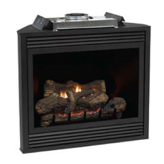
White Mountain Hearth
DVD42FP3P-2
Owner's Manual
Shop genuine replacement parts for White Mountain
Hearth DVD42FP3P-2
Find Your White Mountain Hearth Fireplace Parts - Select From 539 Models
-------- Manual continues below --------
Advertisement
Table of Contents
Troubleshooting

Related Manuals for Empire Comfort Systems DVD FP3 Series


Summary of Contents for Empire Comfort Systems DVD FP3 Series
- Page 1 This Owner's Manual is provided and hosted by Appliance Factory Parts. White Mountain Hearth DVD42FP3P-2 Owner's Manual Shop genuine replacement parts for White Mountain Hearth DVD42FP3P-2 Find Your White Mountain Hearth Fireplace Parts - Select From 539 Models -------- Manual continues below --------...
- Page 2 INSTALLATION INSTRUCTIONS AND OWNER’S MANUAL GAS-FIRED INSTALLER: Leave this manual with the appliance. CONSUMER: Retain this manual for future reference. DIRECT VENT ZERO CLEARANCE GAS Carton Contents FIREPLACE HEATER SERIES: Accessory Sheet Rockwool Hardware Pack Registration Card AA Battery (4) (IP only) Power Adaptor (IP only) MILLIVOLT (MV) Junction Box Cover...
-
Page 3: Table Of Contents
TABLE OF CONTENTS SECTION PAGE IMPORTANT SAFETY INFORMATION ............................3 SAFETY INFORMATION FOR USERS OF LP GAS ........................4 REQUIREMENTS FOR MASSACHUSETTS ........................... 5 INTRODUCTION ....................................6 SPECIFICATIONS .................................... 7 VENT SYSTEM IDENTIFICATION ..............................8 SPECIAL VENT SYSTEMS ................................8 FIREPLACE DIMENSIONS ................................ -
Page 4: Important Safety Information
IMPORTANT SAFETY INFORMATION Before enclosing the vent pipe assembly, operate the appliance to ensure it is venting properly. DO NOT OPERATE THIS APPLIANCE WITHOUT GLASS FRONT PANEL INSTALLED • If this appliance is installed directly on carpeting, • Under no circumstances should any solid fuels tile or other combustible material other than wood (wood, coal, paper or cardboard etc.) be used in flooring the appliance shall be installed on a metal... -
Page 5: Safety Information For Users Of Lp Gas
SAFETY INFORMATION FOR USERS OF LP GAS Propane (LP-Gas) is a flammable gas which can cause its odor intensity. fires and explosions. In its natural state, propane is odor- LP-Gas may stratify in a closed area, and the odor intensity less and colorless. -
Page 6: Requirements For Massachusetts
REQUIREMENTS FOR MASSACHUSETTS For all side wall horizontally vented gas fueled equipment installed SIGNAGE. A metal or plastic identification plate shall be in every dwelling, building or structure used in whole or in part for permanently mounted to the exterior of the building at a residential purposes, including those owned or operated by the minimum height of eight feet above grade directly in line with Commonwealth and where the side wall exhaust vent termination... -
Page 7: Introduction
The term “qualified agency” means any individual, firm, corporation or company which either in • Installation other than as instructed by Empire Comfort Systems, Inc. person or through a representative is engaged in and is responsible for •... -
Page 8: Specifications
SPECIFICATIONS DVD32 DVD36 DVD42 DVD48 Input BTU/Hr Maximum 18000 (NAT, LP) 20,000 (NAT, LP) 25,000 (NAT, LP) 28,000 (NAT, LP) 14,000 (NAT) 18,000 (NAT) 20,000 (NAT) Input BTU/Hr Minimum (millivolt only) 14,000 (NAT, LP) 16,500 (LP) 19,500 (LP) 22,000 (LP) KWH (Maximum) KWH (Minimum) Orifice NAT... -
Page 9: Vent System Identification
300°F/149°C. The inner flue joints do not require any sealant. Special Venting Components (Simpson Duravent) See Empire Comfort Systems Retail Price List for Simpson Duravent part numbers and pricing. Special DV Vent Kits Available from Empire Comfort Systems, Inc. -
Page 10: Fireplace Dimensions
FIREPLACE DIMENSIONS DVD32 DVD36 DVD42 DVD48 34" 37" 43" 49" 864 mm 940 mm 1092 mm 1245 mm 31" 34" 40" 46" 787 mm 864 mm 1016 mm 1168 mm 23 1/16" 23 1/16" 25 1/16" 25 1/16" 585 mm 585 mm 636 mm 636 mm... -
Page 11: Clearances
CLEARANCES Mantel Chart Clearance to Combustibles Back 0" (0 mm) Side 0" (0 mm) Floor 0" (0 mm) Top Stand-off 0" (0 mm) Top Framing Edge 3" (76 mm) Figure 5 Clearances Clearance from top front edge of fireplace to ceiling is 36" Figure 3 Clearance from side of fireplace to adjacent sidewall is 6". -
Page 12: Locating Fireplace
LOCATING FIREPLACE Note: Island and Room Divider installation is possible as long as the horizontal portion of the vent system does not exceed 20 feet with a minimum vertical run of 8 feet. See details in Venting Section. When you install your Direct Vent Fireplace in Room divider or Flat on wall corner positions, a minimum of six inches clearance must be maintained from the perpendicular wall and the front edge of the appliance. -
Page 13: Gas Supply
GAS SUPPLY The gas pipeline can be brought in through the right or left side of Installing a New Main Gas Cock the appliance. Consult the current National Fuel Gas Code, ANSI Each appliance should have its own manual gas cock. Z223.1 CAN/CGA-B149 (.1 or .2) installation code. -
Page 14: Installation
INSTALLATION Framing and Finishing Vent Pipe Clearance Note: Maintain one inch of clearance around vertical vent pipe. See Choose unit location. Frame in fireplace with a header across the top. It is important Figure 11. For horizontal vent, maintain a minimum 1” clearance to to allow for finished face when setting the depth of the frame. - Page 15 INSTALLATION (continued) Note: For finishing to top of fireplace, refer to Figure 14. Flush Mount Mantel Installation The fireplace must extend 3/4" beyond finished wall surface when using a flush mount mantel. Refer to Figure 13 to locate nailing flanges on fireplace sides. Mark and drill two 1/8" holes into fireplace side to mount each nailing flange.
- Page 16 INSTALLATION (continued) Flush Wall Installation Attention: Cold climate installation recommendation: When installing this unit against a non-insulated exterior wall, it is recommended that the outer walls be insulated to conform to applicable insulation codes. Vent Runs In planning the installation for the fireplace, it is necessary to install certain components before the appliance is completely positioned and installed.
- Page 17 INSTALLATION (continued) HORIZONTAL ONLY, STRAIGHT OUT THE BACK "A" "B" Models 5 1/8" to 6 1/2" 6" DVD 32,36,42,48 (130 mm to 165 mm) 8 1/8" to 9 1/2" 9" DVD 32,36,42 (206 mm to 241 mm) 11 1/8" to 12 1/2" 12"...
- Page 18 INSTALLATION (continued) CORNER INSTALLATION VERTICAL, 90° ELBOW TO HORIZONTAL OUT THE WALL Dim. DVD32 DVD36 DVD42 DVD48 36 1/8" 38 3/8" 42 1/2" 46 3/4" 918 mm 975 mm 1080 mm 1187 mm 25 1/2" 27 1/8" 30 1/8" 33 1/8" 648 mm 689 mm 765 mm...
-
Page 19: Venting Fireplace - Top
VENTING FIREPLACE - TOP To Use the Vent Graph Venting Graph (Dimensions in Feet) 1. Determine the height of the center of the horizontal vent pipe. Using this dimension on the Sidewall Vent Graph, locate the point it intersects with the slanted graph line. 2. - Page 20 VENTING FIREPLACE - TOP (continued) Below Grade Installation When it is not possible to meet the required vent terminal clearances of 12” (305 mm) above grade level, a snorkel kit is recommended. It allows installation depth down to 7” (178 mm) below grade level. The 7”...
- Page 21 VENTING FIREPLACE - TOP (continued) Cutting the Hole After the fireplace has been positioned in its permanent location, the hole through the exterior wall of the house can be cut. This hole must be 11" (280mm) high x 10" (254mm) wide with its center line determined by the amount of vertical rise and horizontal run of the termination.
-
Page 22: Examples - Top Vent Run
EXAMPLES - TOP VENT RUN Figure 30 Figure 29 Figure 31 31629-13-1215 Page 21... -
Page 23: Venting Fireplace - Rear
VENTING FIREPLACE - REAR Venting Graph (Dimensions in Feet) To Use the Vent Graph 1. Determine the height of the center of the horizontal vent pipe. Using this dimension on the Sidewall Vent Graph, locate the point it intersects with the slanted graph line. -
Page 24: Examples - Rear Vent Run
EXAMPLES - REAR VENT RUN Model Maximum Pipe Length H1 DVD32 24" DVD36 24" DVD42 24" DVD48 6" Figure 35 Figure 33 Model Maximum Pipe Length H1 DVD32 24" DVD36 24" DVD42 18" DVD48 Figure 36 Figure 34 31629-13-1215 Page 23... -
Page 25: Rear Vent Conversion
REAR VENT CONVERSION Converting flue take-off to rear venting When switching out the flue and inlet vent collars to run horizontally 4. Reinstall the inlet cover plate over the top inlet opening with 4 off the rear vent, the following steps must be taken. screws. -
Page 26: Vent Clearances
VENT CLEARANCES Figure 37 *Clearance above grade, veranda, porch, deck or balcony clearance to non-mechanical air supply inlet to building or [*12 inches (305 mm) minimum] the combustion air inlet to any other appliance [*12 inches (305 mm) minimum for appliances ≤ 100,000 BTU/Hr (30 clearance to window or door that may be opened [*12 inches (305 mm) minimum for appliances <... -
Page 27: Framing And Finishing
FRAMING AND FINISHING Installing Support Brackets A horizontal pipe support MUST BE used for each 3 feet of horizontal run. The pipe supports should be placed around the pipe and nailed in place to framing members. There MUST BE a 3 inch clearance to combustibles above 6 5/8 inch diameter pipe and elbows and 1 inch clearance on both sides and bottom of 6 5/8 inch pipe to combustibles on all horizontal pipe sections and elbows. - Page 28 FRAMING AND FINISHING (continued) Vertical Firestops Vertical runs of this system which pass through ceilings require the use of ONE ceiling firestop at the hole in each ceiling through which the vent passes. Position a plumb bob directly over the center of the vertical vent component and mark the ceiling to establish the center point of the vent.
-
Page 29: Termination Clearances
TERMINATION CLEARANCES Termination clearance for buildings with combustible and noncombustible exteriors. Figure 43 Vertical Sidewall Installations Important! Minimum clearance between vent pipes and combustible materials is three inches (76 mm) on top, and one inch (25 mm) on bottom and sides. Important! When vent termination exits through foundation less than 20"... -
Page 30: Horizontal Termination
HORIZONTAL TERMINATION NOTE: Termination cap should pass through the wall firestop from For installations requiring a vertical rise on the exterior of the the exterior of the building. Adjust the termination cap to building, 14-inch and 36-inch tall Snorkel Terminations, as shown in its final exterior position on the building. -
Page 31: Vertical Termination
VERTICAL TERMINATION Locate and mark the center point of the vent pipe using a nail on out at joints. Condensate can cause corrosion of caps, pipe and fittings. It may be caused by having excessive lateral runs, too the underside of the roof. Drive the nail through the center point. many elbows and exterior portions of the system being exposed Mark the outline of the roof hole around this center point. - Page 32 Vertical Inlet baffle, DVF-139 combustion chamber must be examined by a qualified service person from your Empire Comfort Systems, Inc. distributor or dealer for for damage. All damaged gaskets on the glass frame assembly and Simpson Duravent only.
-
Page 33: Dvvk-4F Flex Vent Instructions
DVVK-4F FLEX VENT INSTRUCTIONS The DVVK-4F FLEX VENT KIT includes the following compo- Install the Wall Firestop/Thimble assembly as required through the wall. Refer to the venting charts in the fireplace manual to determine nents: the proper height and size of the vent opening. The minimum opening •... -
Page 34: Dvvk-4Re Vent Kit Installation Instructions
DVVK-4RE VENT KIT INSTALLATION INSTRUCTIONS CAUTION: Sharp edges, use protective gloves when installing. Tools Needed for Installation: Sheet metal snips 5/16” nut driver Phillips head screwdriver - #2 High temperature sealant or furnace cement rated for continuous use at 1,000ºF minimum Measuring tape Parts Verification See parts list on page 35 to verify components included in this vent... - Page 35 DVVK-4RE VENT KIT INSTALLATION INSTRUCTIONS (continued) 7. Remove outside mounting plate with tube attached from wall. Mark and cut the extra length of the 6 5/8” (168 mm) diameter tube from the opposite end. Do not crimp or enlarge tube. 8.
- Page 36 DVVK-4RE VENT KIT INSTALLATION INSTRUCTIONS (continued) Follow correct option according to venting method. Connecting to Rigid Vent System If the air inlet and flue outlet tubes are to be connected to a rigid Connecting Directly to Fireplace venting system (and not directly to the back of the unit), then do If the air inlet and flue outlet tubes are to be connected directly to not use the gasket provided.
-
Page 37: Log Placement (5 Log Set) - Dvd(32,36)Fp
LOG PLACEMENT (5 LOG SET) - DVD(32,36)FP This fireplace is supplied with a set of five ceramic fiber logs. Do not handle these logs with your bare hands! Always wear gloves to prevent skin irritation from ceramic fibers. After handling logs, wash your hands gently with soap and water to remove any traces of fibers. -
Page 38: Log Placement (7 Log Set) - Dvd(42,48)Fp
LOG PLACEMENT (7 LOG SET) - DVD(42,48)FP This fireplace is supplied with a set of seven ceramic fiber logs. Do not handle these logs with your bare hands. Always wear gloves to prevent skin irritation from ceramic fibers. After handling logs, wash your hands gently with soap and water to remove any traces of fiber. -
Page 39: Millivolt Operating Instructions (Fp3 Series)
MILLIVOLT OPERATING INSTRUCTIONS (FP3 SERIES) 750 Millivolt System The OWNER should carefully read and follow these operating The standing pilot (750 millivolt system) is a continuous burning instructions at all times. Lower the door assembly to view the gas pilot. The pilot remains ON even when the main burner is OFF. controls for the fireplace. - Page 40 MILLIVOLT OPERATING INSTRUCTIONS (FP3 SERIES) Electric (120 volt) Operated Remote Control, FREC STANDING PILOT OPERATING INSTRUCTIONS Connect the green and red, stripped and bare, wires on the REMOTE/ REMOTE/OFF/ON Switch OFF/ON switch wire harness to the wires on remote receiver that The fireplace is equipped with a REMOTE/OFF/ON switch.
-
Page 41: Millivolt Standing Pilot Wiring Diagram (Fp3 Series)
MILLIVOLT STANDING PILOT WIRING DIAGRAM (FP3 SERIES) Figure 61 Page 40 31629-13-1215... -
Page 42: Millivolt Standing Pilot Lighting Instructions (Fp3 Series)
MILLIVOLT STANDING PILOT LIGHTING INSTRUCTIONS (FP3 SERIES) FOR YOUR SAFETY READ BEFORE LIGHTING WARNING: If you do not follow these instructions exactly, a fire or explosion may result causing property damage, personal injury or loss of life. This appliance has a pilot which must be lighted by hand. C. -
Page 43: Millivolt Standing Pilot Troubleshooting (Fp3 Series)
MILLIVOLT STANDING PILOT TROUBLESHOOTING (FP3 SERIES) With proper installation and maintenance, your new Direct Vent Gas Fireplace will provide years of trouble-free service. If you do experience a problem, refer to the Trouble Shooting Guide below. This guide will assist a qualified service person in the diagnosis of problems and the corrective action to be taken. -
Page 44: Direct Ignition Lighting Instructions (Fp5 Series)
DIRECT IGNITION LIGHTING INSTRUCTIONS (FP5 SERIES) FOR YOUR SAFETY READ BEFORE LIGHTING WARNING: IF YOU DO NOT FOLLOW THESE INSTRUCTIONS EXACTLY, A FIRE OR EXPLOSION MAY RESULT CAUSING PROPERTY DAMAGE, PERSONAL INJURY, OR LOSS OF LIFE. BEFORE LIGHTING smell all around the appliance area for Use only the wall switch or remote control switch to turn the gas. -
Page 45: Direct Ignition Wiring Diagram (Fp5 Series)
DIRECT IGNITION WIRING DIAGRAM (FP5 SERIES) LED CODES Steady ON Normal operation, power ON to control 2 Flashes 3 unsuccessful ignition trials 3 Flashes Main burner flame failed 4 times during a single heating cycle 4 Flashes Interrupt power for 5 seconds to reset control Steady Flash Flame detected out of sequence Figure 62... -
Page 46: Initial Start Up Gas Line Purge (Fp5 Series)
INITIAL START UP GAS LINE PURGE (FP5 SERIES) NOTE: UNIT MUST BE PROPERLY GROUNDED FOR ELECTRONIC IGNITION TO FUNCTION. On initial installation, or after extended periods where the fireplace has not been used, gas lines may require purging. The installer or qualified service person may use the following purge procedures to prevent the delays that would be caused by waiting for the lockout periods between tries for ignition. -
Page 47: Direct Ignition Propane/Lp Gas Conversion (Fp5 Series)
DIRECT IGNITION PROPANE/LP GAS CONVERSION (FP5 SERIES) The conversion shall be carried out in accordance with the 14. Replace main burner onto burner assembly. Place main requirements of the provincial authorities having jurisdiction burner beneath electrodes, slide main burner from right to and in accordance with the requirements of the CSA B149.2 left into burner location, and pivot main burner away from installation code (Canada) and with the requirements of the... -
Page 48: Propane/Lp Gas Conversion (Fp5 Series)
PROPANE/LP GAS CONVERSION (FP5 SERIES) Maxitrol Valve Conversion “A” Model AIR SHUTTER BURNER ORIFICE SETTINGS Opening "A" Propane/LP Orifice DVD32 1/4" (6.4 mm) DVD36 1/4" (6.4 mm) DVD42 5/16" (7.9 mm) 1.45 mm DVD48 5/16" (7.9 mm) 1.55 mm Figure 63 Figure 64 31629-13-1215 Page 47... -
Page 49: Ipi Electronic System Operating Instructions (Fp7 Series)
IPI ELECTRONIC SYSTEM OPERATING INSTRUCTIONS (FP7 SERIES) 5.25 VDC ELECTRONIC CONTROL VALVE OPTIONAL REMOTE CONTROLS The electronic control valve system includes the ability to switch Optional remote controls are available for use with this appliance. the pilot from a standing pilot mode to an intermittent pilot mode. It is recommended that the remote receiver be placed either in a •... -
Page 50: Ipi Electronic System Wiring Diagram (Fp7 Series)
IPI ELECTRONIC SYSTEM WIRING DIAGRAM (FP7 SERIES) If any of the original wire supplied with this unit must be replaced, it must be replaced with equivalent gauge and temperature rated wire. This appliance is only for use with the type of gas indicated on the rating plate in this appliance and may be installed in an aftermar- ket, permanently located, manufactured (mobile) home where not prohibited by local codes. -
Page 51: Intermittent Pilot Lighting Instructions (Fp7 Series)
INTERMITTENT PILOT LIGHTING INSTRUCTIONS (FP7 SERIES) FOR YOUR SAFETY READ BEFORE LIGHTING WARNING: If you do not follow these instructions exactly, a fire or explosion may result causing property damage, personal injury or loss of life. This appliance has a pilot which can be lighted with the C. -
Page 52: Intermittent Pilot Control System Troubleshooting (Fp7 Series)
INTERMITTENT PILOT CONTROL SYSTEM TROUBLESHOOTING (FP7 SERIES) Brief Description of the Components The gas valve is fitted with a manual HI/LO knob to allow for man- ual modulation of the gas outlet pressure to the appliance burner. The controls are designed to be used with either LPG or Natural Gas and can be converted by use of an OEM supplied conversion kit. - Page 53 INTERMITTENT PILOT CONTROL SYSTEM TROUBLESHOOTING (FP7 SERIES) Page 52 31629-13-1215...
- Page 54 INTERMITTENT PILOT CONTROL SYSTEM TROUBLESHOOTING (FP7 SERIES) 31629-13-1215 Page 53...
-
Page 55: Maintenance And Service
MAINTENANCE AND SERVICE PLEASE NOTE WARNING: It is normal for appliances fabricated of steel to give off 1. The use of substitute glass will void all product warranties. some expansion and/or contraction noise during the start 2. Care must be taken to avoid breakage of the glass. up or cool down cycle. -
Page 56: Master Parts Distributor List
This list changes from time to time. For the current list, please click on the Master Parts button at www.empirecomfort.com. Please note: Master Parts Distributors are independent businesses that stock the most commonly ordered Original Equipment repair parts for Heaters, Grills, and Fireplaces manufactured by Empire Comfort Systems Inc. Dey Distributing Victor Division of F. -
Page 57: Dvd32Fp(3,5,7) Parts List
DVD32FP(3,5,7) PARTS LIST PART NUMBER PART NUMBER INDEX INDEX DESCRIPTION DESCRIPTION (FP3) (FP5) (FP7) (FP3) (FP5) (FP7) R7654 R7654 R7654 FLUE INSULATION P212 P212 P212 ORIFICE FITTING FLUE INSULATION RE- TUBING ASSEMBLY, 17425 17425 17425 17258 23550 31570 TAINER INLET R7566 R7566 R7566... -
Page 58: Dvd32Fp(3,5,7) Parts View
DVD32FP(3,5,7) PARTS VIEW USE ONLY MANUFACTURER’S REPLACEMENT PARTS. USE OF ANY OTHER PARTS COULD CAUSE INJURY OR DEATH. 31629-13-1215 Page 57... -
Page 59: Dvd36Fp(3,5,7) Parts List
DVD36FP(3,5,7) PARTS LIST PART NUMBER PART NUMBER INDEX INDEX DESCRIPTION DESCRIPTION (FP3) (FP5) (FP7) (FP3) (FP5) (FP7) R7654 R7654 R7654 FLUE INSULATION R7572 R7572 R7572 JAMB NUT FLUE INSULATION P212 P212 P212 ORIFICE FITTING 17425 17425 17425 RETAINER TUBING ASSEMBLY, 17258 23550 31570... -
Page 60: Dvd36Fp(3,5,7) Parts View
DVD36FP(3,5,7) PARTS VIEW 31629-13-1215 Page 59... -
Page 61: Dvd42Fp(3,5,7) Parts List
DVD42FP(3,5,7) PARTS LIST PART NUMBER PART NUMBER INDEX INDEX DESCRIPTION DESCRIPTION (FP3) (FP3) (FP7) (FP3) (FP3) (FP7) R7654 R7654 R7654 FLUE INSULATION P286 P286 P286 ORIFICE (NAT) FLUE INSULATION P208 P208 P208 ORIFICE (LPG) 17425 17425 17425 RETAINER R7572 R7572 R7572 JAMB NUT R7566... -
Page 62: Dvd42Fp(3,5,7) Parts View
DVD42FP(3,5,7) PARTS VIEW 31629-13-1215 Page 61... -
Page 63: Dvd48Fp(3,5,7) Parts List
DVD48FP(3,5,7) PARTS LIST PART NUMBER PART NUMBER INDEX INDEX DESCRIPTION DESCRIPTION (FP3) (FP3) (FP7) (FP3) (FP3) (FP7) R7654 R7654 R7654 FLUE INSULATION P285 P285 P285 ORIFICE (NAT) FLUE INSULATION P258 P258 P258 ORIFICE (LPG) 17425 17425 17425 RETAINER R7572 R7572 R7572 JAMB NUT R7566... -
Page 64: Dvd48Fp(3,5,7) Parts View
DVD48FP(3,5,7) PARTS VIEW 31629-13-1215 Page 63... -
Page 65: Fbb4 Optional Variable Speed Blower Installation
FBB4 OPTIONAL VARIABLE SPEED BLOWER INSTALLATION Attention: Install blower assembly before connecting gas inlet 5. Insert blower assembly into interior, bottom of fireplace. supply line Position blower assembly behind gas valve, align notch on back of blower assembly with center screw on fireplace Note: Junction box on right side of fireplace must be pre-wired at back and push blower assembly against fireplace back. - Page 66 FBB4 OPTIONAL VARIABLE SPEED BLOWER INSTALLATION R7731 BLOWER ASSEMBLY 31920 SWITCH ASSEMBLY R4192 SPEED CONTROL KNOB R4186 SPEED CONTROL 31629-13-1215 Page 65...
-
Page 67: Junction Box Wiring Installation Instructions
JUNCTION BOX WIRING INSTALLATION INSTRUCTIONS STANDARD MILLIVOLT VALVE MODELS CAUTION: ALL WIRING SHOULD BE DONE BY A QUALIFIED ELECTRICIAN AND SHALL BE IN COMPLIANCE WITH ALL LOCAL, CITY AND STATE BUILDING CODES. BEFORE MAKING THE ELECTRICAL CONNECTION, MAKE SURE THAT MAIN POWER SUPPLY IS DISCONNECTED. -
Page 68: Accessories
ACCESSORIES The following accessory parts can be obtained from your Empire Comfort Systems dealer. If you need additional information beyond what your dealer can furnish, contact Empire Comfort Systems Inc., Nine Eighteen Freeburg Ave., Belleville, Illinois 62220-2623. Accessory Description Model Number Fan Kit This fan kit is designed to provide forced air flow. -
Page 69: Decorative Accessories
DECORATIVE ACCESSORIES Decorative Door Decorative Door Decorative Frame (with hinges) Mission Rectangle Plain Rectangle Note: Decorative Frame required for use with Empire Comfort Systems Decorative Door. Decorative Door Decorative Door Mission Arch Plain Arch Window Trim Standard Louvers 45 Degree... -
Page 70: Warranty
WARRANTY Empire Comfort Systems Inc. warranties this hearth product to be free from defects at the time of purchase and for the periods speci- fied below. Hearth products must be installed by a qualified technician and must be maintained and operated safely, in accordance with the instructions in the owner’s manual. -
Page 71: Appliance Service History
APPLIANCE SERVICE HISTORY Date Dealer Name Service Technician Name Service Performed/Notes Page 70 31629-13-1215... - Page 72 APPLIANCE SERVICE HISTORY Date Dealer Name Service Technician Name Service Performed/Notes 31629-13-1215 Page 71...
- Page 73 Empire Comfort Systems Inc. EMPIRE EMPIRE 918 Freeburg Ave. Belleville, IL 62220 If you have a general question about our products, please e-mail us at info@empirecomfort.com. If you have a service or repair question, please contact your dealer. Comfort Systems www.empirecomfort.com...
Need help?
Do you have a question about the DVD FP3 Series and is the answer not in the manual?
Questions and answers