Table of Contents
Advertisement
Quick Links
MTS250PHF
Operators's Manual
Safety, Setup and General Use Guide
REV.2 0 00144-16
Issue Date: May. 10, 2016
Manual No.: 0-1534
(Suitable for 1x110V or 1x220V)
EMPRESAS CARBONE S.A.
Calle 5ta. Rio Abajo, Panamá, Panamá
Telefonos: (507) 3916309 / 3916313
www.empresascarbone.com
IGBT INVERTER
DC-MMA/TIG/CO
WELDING MACHINE
2
Advertisement
Table of Contents

Related Manuals for CARBONE MTS250PHF


Summary of Contents for CARBONE MTS250PHF
- Page 1 DC-MMA/TIG/CO WELDING MACHINE (Suitable for 1x110V or 1x220V) Operators’s Manual Safety, Setup and General Use Guide EMPRESAS CARBONE S.A. REV.2 0 00144-16 Calle 5ta. Rio Abajo, Panamá, Panamá Issue Date: May. 10, 2016 Telefonos: (507) 3916309 / 3916313 Manual No.: 0-1534...
- Page 2 Dear Customer, Thank you for selecting the our machine. We appreciate you as a customer and hope that you will enjoy years of use from your welder. Please go directly to the our website to register your unit and receive your warranty information. Your unit registration is important should any information such as product updates or re-calls be issued.
- Page 3 Please record your equipment identification below for future reference. This information can be found on data plate at rear of machine. Product MTS250PHF : Serial No. ___________________________________ Date of Purchase _____________________________ Where Purchased _____________________________...
-
Page 4: Safety Precautions
SAFETY PRECAUTIONS We are dedicated to providing you with the best possible equipment and service to meet the demanding jobs that you have. We want to go beyond delivering a satisfactory product to you. That is the reason we offer technical support to assist you with your needs should an occasion occur. With proper use and care your product should deliver years of trouble free service. - Page 5 SAFETY PRECAUTIONS These safety precautions are for protection of safety and health. Failure to follow these guidelines may result in serious injury or death. Be careful to read and follow all cautions and warnings. Protect yourself and others. Welding and cutting processes produce high levels of ultraviolet (UV) radiation that can cause severe skin burn and damage.
- Page 6 SAFETY PRECAUTIONS WARNING! Persons with pacemakers should not weld, cut or be in the welding area until they consult with their physician. Some pacemakers are sensitive to EMF radiation and could severely malfunction while welding or while being in the vicinity of someone welding. Serious injury or death may occur! Welding and plasma cutting processes generate electro-magnetic fields and radiation.
- Page 7 SAFETY PRECAUTIONS WARNING! Electrical shock can kill. Make sure all electrical equipment is properly grounded. Do not use frayed, cut or otherwise damaged cables and leads. Do not stand, lean or rest on ground clamp. Do not stand in water or damp areas while weld-ing or cutting. Keep work surface dry.
-
Page 8: Table Of Contents
TABLE OF CONTENTS Page SAFETY PRECAUTIONS..........Installation.............Section A Technical Specifications..........A-1 Output Amps %duty cycle ..........A-2 Select Suitable Location..........A-3 Stacking ..............A-3 TRANSPORT - UNLOADING ..........A-3 Tilting...............A-3 Environmental Area ............A-3 Machine Grounding and High Frequency Interference Protection ..A-4 Input Connections ...........A-4 Reconnect Procedure............A-5 220/230/240V Input.............A-5... -
Page 9: Installation
INSTALLATION TECHNICAL SPECIFICATIONS max. rated Output Amps @% Duty Cycle (Based on a 10 minute cycle) (Example; 250A@35% for MIG&TIG and 200A@35% for DC Stick) MODEL MTS250PHF Voltage 1 xAC110V 50/60Hz 1 xAC220V 50/60Hz Rated Input current 39 A 40 A... - Page 10 INSTALLATION Chart gives max. rated Output Amps @% Duty Cycle (Based on a 10 minute cycle) (Example; 250A@35% for MIG&TIG and 200A@35% for DC Stick) Using standard input cable for protected input supply 100% TIG &MIG STICK(MMA) OUTPUT AMPS Wiring and protection based on the IEC60974.1 National Electric Code: Use a Super Lag type fuse or circuit breaker with a delay in tripping action.
-
Page 11: Select Suitable Location
INSTALLATION SAFETY PRECAUTIONS Read entire installation section before starting installation. Neither let the equipment or the single unit fall, nor put it down with force. Once it has been removed from the packing, the ELECTRIC SHOCK can kill. power source can be used to move it in the ·Only qualified personnel should hand or on the shoulder. -
Page 12: Machine Grounding And High Frequency Interference Protection
INSTALLATION MACHINE GROUNDING AND HIGH following methods: FREQUENCY INTERFERENCE a) A metal underground water pipe in direct contact PROTECTION with the earth for ten feet or more. This welder must be grounded! See your local and b) A 3/4" (19mm) galvanized pipe or a 5/8" national electrical codes for proper grounding (16mm)solid galvanized iron, steel or copper rod methods. -
Page 13: Reconnect Procedure
INSTALLATION 1Also called “inverse time” or “thermal/magnetic” Using fuses or circuit breakers smaller than circuit breakers. recommended may result in "nuisance" shut-off These circuit breakers have a delay in tripping from welder inrush currents even if not welding at action that decreases as the magnitude of the current increases. -
Page 14: Work Cable Connection
INSTALLATION ENGINE DRIVEN GENERATOR CONNECTIONS FOR MIG WELDING The Inverter machine can be operated on engine driven generators as long as the 220/230/240 volt auxiliary meets the following conditions: . The AC waveform peak voltage is below 400 volts. . The AC waveform frequency is between 45 and 65Hz. - Page 15 INSTALLATION CONNECTIONS FOR STICK (SMAW) WELDING A. POSITIVE CONNECTION B . NEGATIVE CONNECTION STICK ELECTRODE CABLE AND WORK CABLE CONNECTION Refer to Field Installed Options in Accessories Section this manual STICK welding equipment which is available for use with the inverter machine.
-
Page 16: Operation
OPERATION Read and understand this entire section before operating the machine. SAFETY PRECAUTIONS ELECTRIC SHOCK can kill. · Do not touch electrically live parts or electrode with skin or wet clothing. · Insulate yourself from work and ground. · Always wear dry insulating gloves. Read and follow "Electric Shock Warnings"... -
Page 17: Product Description
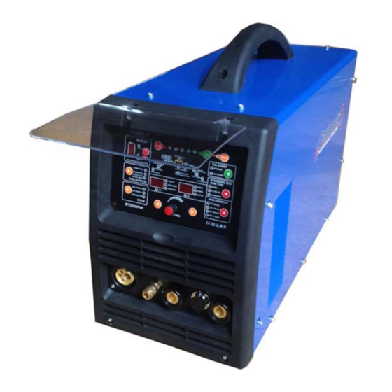
OPERATION PRODUCT DESCRIPTION PROCESS LIMITATIONS The MTS250PHF is a versatile and compact MIG/Stick welder The machines are not recommended for arc gouging due to capable of delivering professional quality welds. Operating on it's limited output capacity, and are also not recommended for an input of 110V or 220V 50/60Hz (1 phase), the CC/CV IGBT pipe thawing. -
Page 18: Controls And Settings
OPERATION CONTROLS AND SETTINGS FIGURE B.1 CONTROL PANEL FRONT PANEL 1 Voltage /MMA arcforce/up down slope /post /pre flow time et. Display meter a、The meter on the front panel can indicate the actual welding voltage or preset MIG voltage.The indicating number has the precision of 0.1V .The meter indicates the preset during no welding. b、display MIG up &down slope time/post & pre flow time/MIG burnback time/hot start time c、display MMA arcforce/MIG inductance /pulse time on/hot start current/(base/pulse) percent 2 Current /wire speed/pulse freq. Display meter The current indicating meter on the front panel indicates the actual welding current during the welding, indicates the preset current during no welding. ... - Page 19 OPERATION speed and voltage. 10 Duty Cycle/Overcurrent Warning. 19TIG start Selector When the duty cycle has been exceeded or an 20 TIG Process Selector overcurrent, condition has occurred, the L.E.D. will light. Allow the unit to cool while running until the light goes off or for 10 minutes before resetting ...
- Page 20 OPERATION SIDE VIEW...
- Page 21 OPERATION Side Panel Description and Explanation: energized for a short time after the wire feeder 1. Wire Spool Carrier Assembly. Make stops feeding . The wire will burn back to the note of the correct assembly order if disassembled. desired length by adjusting the control. This The order in which they are assembled is im‐proves re‐starts and keeps the user from im‐portant to be able to provide enough hav‐ing to re‐trim the wire between welds. re‐sistance to prevent de‐spooling of the wire. NOTE: Too much burn back time may When inserting the spool , make sure the small tab cause the wire to burn back to far and seize to the on the inside of the spool holder is located in one tip. of the recesses made into the spool, if any. Tighten 4. Wire Feed Assembly. Note the numbers the hex head screw under the hand nut after on the side of the tensioner. These numbers are a reference point to help properly tension the wire so that installing the wire spool so that the wire will not the drive roller will not slip. Do not over‐tension the continue to keep rolling more than a 1/4 turn after wire because it can create a condition known as birds wire has stopped feeding. Do not over tighten so nesting, where the wire will tangle up around the feeder that the drive roller slips or the feeder strains to and will not slip if the wire burns back into tip, sticks fast pull the wire due to excessive resistance. The in the weld puddle or other resistance is met. This will tensioner assem‐bly can accommodate 8” spools continue wrap the wire around the drive mechanism or of wire (10‐12 lbs.) However, a simple center jam wire inside the gun liner until the trigger is released. ...
- Page 22 OPERATION REAR VIEW/BACK PANEL Rear Panel: 1. Gas Supply. Connect the Gas regulator hose to this point via the brass barb fitting. (Regulator is customer supplied and not provided as standard equipment at time of publication.) The hose barb connection must be tight to prevent gas leakage. Install extra clamp if needed to prevent gas from escaping. 2. Power Switch. Turns unit on or off. The “I” mark indicates on. And the “O” mark indicates off. These are universally accepted symbols for On and off. 3. Power Input Cable and NEMA 6‐50P Plug. USE THE 220V TO 110V ADAPTER TO SAFELY ADAPT THE NEMA 6-50P (INDUSTRY STANDARD 240V WELDER PLUG) TO THESTANDARD NEMA 5-15P WHEN OPERATING ON 110V. THIS PLUG ADAPTER PRESERVES THE POLARITY REQUIREMENT FOR OPERATION ON 110V.
-
Page 23: Operating Steps
OPERATION OPERATING STEPS WELDING IN MIG MODE... - Page 24 OPERATION TO THREAD WIRE INTO FEEDER: 1. Loosen top idler tensioner, rotating counter-clockwise 2. Flip tensioner down, releasing top drive roll. 3. Raise top drive idler roller. 4. Inspect the drive roll to make sure that the groove size matches the wire diameter. Reversal of the lower roller may be necessary.
- Page 25 B-10 OPERATION B-10 GENERAL NOTES: 1. While welding aluminum with the Spool gun or MIG gun you must use 100% argon. You cannot use a mix as you would with steel or stainless. 2. While welding aluminum with the Spool gun or MIG gun you must use the next size up tip or a special oversize tip for the wire because the heat will cause the aluminum wire to swell and it will either drag or seize in the tip. 3. While welding aluminum with the MIG process, best results are achieved by using a dedi‐cated stainless steel brush to remove the oxide layer and acetone or aluminum cleaner before welding. Even though aluminum may appear shiny and clean, it still has an oxide layer, and a thin layer of oil left over from the manufacturing process. Some soot will ap‐pear in most MIG welds but if a lot is noticed, you have either contaminated metal, or in‐sufficient gas flow. You can also induce turbulence by having too much of a torch angle. Start with a 90 degree angle and then lean the gun slightly (about 15 degrees) to the “push” position. 4. Welding aluminum is not a short circuit process. It is a spray transfer process. Spray trans‐fer is a process that is can be used to weld many metals, but in Aluminum it must be used to weld correctly. In spray transfer, the wire does not short out against the weld material. Instead a steady “spray” of droplets of molten metal pinches off before the wire can con‐tact the material. It is a much quieter process. If you are not familiar with the spray trans‐fer process, please research it before you try it. If you incorrectly adjust the welder while welding aluminum in the MIG process, you will burn up contact tips almost instantly. 5. If you are trying to weld Aluminum with . 025 wire or smaller, you may not achieve ade‐quate results because of the higher wire feed speeds needed. Try stepping up to the next wire size and wire feed speed rate requirements will drop. 6. If using with a generator, use with only a generator rated or certified for clean power out‐put. This a rating given by the manufacturer of the generator if the total harmonic distor‐tion is 10% or less (usually 5% or less). A generator that does not produce clean power can cause erratic operation and damage to the welder’s electronics. Ideally a generator capable of generating 3500 watts or more should be used. 7. MIG burn back is a common condition where the wire may burn back and fuse with the contact tip while welding or after the trigger is released. If the burn back is slight, allow the tip to cool slightly and remove the tip from the gun feeding extra wire as necessary to get the tip fully removed. Usually, with a ...
- Page 26 B-11 OPERATION B-11...
- Page 27 B-12 OPERATION B-12 General operation and setup. 1) Wire Tension. Always check wire tension before use. Use no more wire tension than is necessary. (See page 15 for adjustment.) 2) Work Clamp. MIG welders require good work clamp (ground) contact. Routinely inspect work clamp and cable and make sure they are in good condition and that the cables are held tight in the connectors and are free of corrosion. Always grind a small clean spot where the work clamp is to be attached. Always connect the work clamp directly to the metal being welded if possible. Hard starting or “machine gunning” at the start of the weld may be a result of a poor ground. 3) MIG gun use and maintenance. Before use make sure that collar on the Euro quick connect has been fully tightened by hand. Do not use tools. Grip the gun firmly when starting the arc to prevent push‐off and spattering/popping at the start of the weld. Trim the wire to 1/2” or less and hold the gun just as close to the metal to start the weld. Use nozzle dip or a anti spatter spray to help keep the MIG gun nozzle from becoming plugged with slag. Reg‐ularly check and clean the nozzle. Nozzle dip and anti spatter can be bought at almost any welding supply store. It is an economical way to prevent harmful accumulation of slag in and on the nozzle and can be used in the weld area to prevent spatter from sticking to the work‐piece. Do not apply too much to the nozzle or directly to the weld area or porosity may occur. Only apply when the protective qualities begin to dissipate. Nozzle dip and anti spatter also provide some lubricity to the contact tip and increases the lifespan and ease of feeding. Make sure to change contact tip size when changing the wire size. Using too large of a contact tip can cause erratic arc behavior. Using too small of a contact tip can cause jamming. When welding with aluminum, use a special alumi‐num contact tip or at least one size larger regular contact tip to accommodate the wire as it expands due to the heat. Over time, the gun liner may be‐come gradually fouled with dirt, metal filings from the coating and other possible contaminants. To prevent this, regularly remove the wire from the cable, and blow dry compressed air down the gun neck with the contact tip removed. If necessary remove the liner and replace it if becomes worn and irregular or difficult feeding or gas flow is ob‐served. NOTE: (Binzel/Trafimet 15 series) When removing the shielding gas nozzle, twist the nozzle like a screw to install or remove as it grips the noz‐zle tightly. There is a special retaining spring un‐der the nozzle that acts as a thread. This feature allows you to position the nozzle in order to vary the depth of the contact tip for different welding applications. 4) Shielding gas selection and use. For MIG opera‐tion, selection of the proper shielding gas is im‐portant. Remember, each shielding gas mixture and filler metal thickness will require a different setting of voltage and amps. A 75/25 (75% Ar‐gon/25%CO2) mixture is recommended for general purpose steel welding. This yields the best results in most circumstances. To reduce spatter further, other blends of Ar/CO2 with higher percentages of Argon (a true inert gas) may be used. The puddle may be difficult to ...
- Page 28 B-13 OPERATION B-13 5) Regulator and shielding gas flow adjustment. NOTE: Regulators may be supplied in LPM or CFH. Please note which has been provided before starting to weld for future reference. The regula‐tor should always be mounted nearly vertical if not with a slight upturn (for safety) so that the ball may float free. Always stand to the opposite side of the regulator and slowly open the regulator with the front and top of the regulator facing away from you. Gas flow requirements vary in MIG greatly and a lot depends upon the environment. More gas will be required in open/drafty areas. To avoid wasting shielding gas, perform some preliminary test welds. To adjust, decrease gas flow until the weld begins to bubble and exhibit porosity. Gradu‐ally increase the gas flow until the bubbles disap‐pears completely. Crack the adjustment on the regulator an small additional amount to ensure full gas coverage. This process will reduce waste and help ensure you are not introducing oxygen into the weld. As the pressure drops within the cylin‐der readjustment may be necessary. 6) MIG polarity. When using solid MIG wire, the polarity should always be electrode positive. This means the torch should always be connected to the positive (+) terminal when welding with solid wire. To check this, open the cover, and inspect the heavy power cable that runs from the front end of the wire feeder to the bolted terminals on the center divider wall that are marked either with a positive (+) sign or a negative (‐) sign. The cable should be screwed down to the terminal marked with the (+) sign for solid wire. For flux core, most (but not all) manufacturers of flux core wire specify the use of negative (‐) polarity. Consult the manu‐facturer’s recommendations regarding flux core or dual shield wire polarity before installation. If neg‐ative polarity is required, swap the feeder cable to the negative terminal. Always make sure the ter‐minal screw is fully tightened. Do not over tighten the terminal or it may strip out the terminal threads. If, after switching between solid and flux core wire, an erratic arc is noticed, double check the polarity. This is a commonly overlooked part of the changeover procedure. 7) Volt and Amp adjustment. The welder features infinite adjustment of voltage and wire feed speed within each range. Wire speed adjustment is di‐rectly related to amp output and the terms are generally used interchangeably. As wire speed in‐creases so does amperage and vice versa. In many welding charts and calculators, you may find actual amperage settings rather than a wire speed setting. Amperage output also depends upon the diameter of the wire as well. Both volts and amps are cali‐brated in numbers ranging from 1‐10 with infinite adjustment possibility between each number. These are relative numbers and are used only as a reference when repeating the same or similar set‐ up. If helpful for setting up the unit, the numbers 1‐10 can be thought of as representing 10%‐100% of full output for either voltage or wire speed. For each wire diameter, most users will find 3 to 5 settings that will fit their welding style and applica‐tions but often the ability to fine tune these settings for specific applications will be needed. At first, some experimentation will be necessary. The fol‐lowing method of setting up wires peed and voltage is commonly used by professionals in the industry to setup ...
- Page 29 B-14 OPERATION B-14 used, burn through can occur, especially on thin gauge material. If welding thin materials such as used in exhaust systems or body work, make sure the wire speed is adjusted to reduce penetration before attempting a voltage change. General figures for both wire speed and amps can be easily determined. To determine wire speed, simply press the trigger (without welding) and hold it for 15 seconds. Measure the length of the wire that is run from the torch in 15 seconds and multiply by 4. This figure is your wire speed in inches per minute (IPM). To roughly determine amps, which are sometimes used by manufacturers for recommend‐ed settings, use the following formulas for the fol‐lowing wire thicknesses: .023”: IPM/3.5 = Amps .030”: IPM/2 = Amps .035”: IPM/1.6 = Amps The actual constant given in this formula represents “inches per amp”. This formula is only a guide and is only accurate in lower ranges as the function is not tru‐ly linear. But it usually will be within the overall range specified by the manufacturer. For each manufacturer, the filler wire diameter amp range may differ some‐what, though a general range can be established. Spool Gun. T he spool gun is an optional, but use‐ful tool to have for welding small and medium projects aluminum projects that are 3/32” and over in thickness. The spool gun connects directly in place of the regular MIG gun. The Spool gun picks up the gas and power at the Euro connection with a separate control connection for the trigger on the spool gun. Once the spool gun panel switch is flipped, the trigger will control on and off operation of the gun. Wire speed and voltage are still controlled at the panel however. NOTE: Some guns Our company sells may have a separate control mounted on the spool gun handle for wire speed, but is inoperative and is not used with this unit. When welding aluminum, the unit should be welded in the spray arc mode. Typically spool guns are good for welding 3/32” and thicker aluminum. Spray arc mode is a mode where the voltage is increased to near maxi‐mum voltage for this unit, and wire speed is adjusted so that the wire melts in a steady stream of consistently sized droplets before the wire contacts the metal. A slight hiss will be present if done correctly. There is a threshold for spray arc, and it requires higher voltage and increased wire speed to force it into this mode. This is a quieter mode ...
- Page 30 B-15 OPERATION B-15 SYNERGIC AND BASIC MIG OPERATION Synergic vs. Manual Setup and Operation How Synergic MIG operates: The Synergic function of the MIG component allows the user to only need to use the wire feed speed control to make the unit operate. The welder is programmed to automatically adjust the voltage based off the users input of wire diameter, and filler metal type when the wire speed is increased or decreased by turning the wire speed adjustment knob. While in the Synergic mode, the user can make manual adjustment to “fine tune” the voltage if he chooses by turning the voltage up or down after adjusting the ...
-
Page 31: Welding In Tig Mode
B-16 OPERATION B-16 concentrates on the anode (workpiece). Narrow and deep welds are obtained with high travel speeds. OPERATING STEPS Most materials, with the exception of aluminum and WELDING IN TIG MODE magnesium, are welded with this polarity. 1 Connect the TIG torch and cable Twist-Mate quick connect plug to the Electrode/Gas output receptacle. - Page 32 B-17 OPERATION B-17 Increasing frequency constricts arc, increases stability and improves weld quality. FIGURE B.6 I(A) DC TIG-NOT PULSED I(A) DC PULSED TIG STEEL TIG WELDING The TIG process is very effective for welding both carbon steel alloy steel, especially applications requiring precision...
- Page 33 B-18 OPERATION B-18 · GTAW Process Approximate Argon Electrode Polarity Electrode Tip Sharpened Gas Flow Rate Preparation Electrode Type EWTh-1, EWLa-1 C.F.H. (l/min.) EWTh-2, EWCE-2 Electrode Stainless Aluminum Size-in. (mm) Steel .010 (0.25) Up to 15 A. 3-8 (2-4) 3-8 (2-4) .020 (0.50) Up to 15 A.
- Page 34 B-19 OPERATION B-19 DC TIG WELDING QUICK START UP the relaxed position, with no thumb pressure. "Maximum" refers to a fully depressed Foot ELECTRIC SHOCK can kill. Ampcontrol,or a fully extended Hand Ampcontrol. . Have an electrician install When the welder is in TIG modes activating the and service this equipment.
- Page 35 B-20 OPERATION B-20...
- Page 36 B-21 OPERATION B-21...
- Page 37 B-22 OPERATION B-22 WELDING IN STICK MODE 1 Put the electrode holder and cable quick connect plug into the electrode output receptacle. Turn clockwise until tight. Connect the work clamp to the work piece. 2 Set the switch to "MMA". 3 Set the Switch to the MMA mode desired for the type of electrode being used (most commonly DC+).
-
Page 38: Maintenance
MAINTENANCE SAFETY PRECAUTIONS ELECTRIC SHOCK can kill. ● Only qualified personnel should per-form this maintenance. ● Turn the input power OFF at FAN MOTOR OR FAN BLADE REPLACEMENT the disconnect switch or fuse When installing a new fan blade or fan motor be box before working on this equipment. -
Page 39: Troubleshooting
TROUBLESHOOTING HOW TO USE TROUBLESHOOTING GUIDE Service and Repair should only be performed by our Factory Trained Personnel. Unauthorized repairs performed on this equipment may result in danger to the technician and machine operator and will invalidate your factory warranty. For your safety and to avoid Electrical Shock, please observe all safety notes and precautions detailed throughout this manual. - Page 40 TROUBLESHOOTING Observe all Safety Guidelines detailed throughout this manual ...
- Page 41 DIAGRAMS Diagram for the MTS250PHF working elements. NOTE: This diagram is for reference only. It may not be accurate for all machines covered by this manual. If the diagram is illegible, write to the Service Department for a replacement. Give the equipment code number.
-
Page 42: Accessories
Operation instructions Certificate of quality ━━━━━━━━━━━━━━━━━━━━━━━ Certificate of quality Name of product: MIG/MAG/TIG/MMA Semi-auto ARC Welding Machine Type of product: MTS250PHF Packing Test results of this welder fulfils_____________ _________technical requirements and its release from the works is granted. Inspector_________ Date___________... - Page 43 Do not touch electrically live parts or Keep flammable materials away. Wear eye, ear and body protection. WARNING electrode with skin or wet clothing. Insulate yourself from work and ground. Spanish No toque las partes o los electrodos Mantenga el material combustible Protéjase los ojos, los oídos y el AVISO DE bajo carga con la piel o ropa moja-...
- Page 44 Keep your head out of fumes. Turn power off before servicing. Do not operate with panel open or Use ventilation or exhaust to guards off. WARNING remove fumes from breathing zone. Spanish Los humos fuera de la zona de res- Desconectar el cable de ali- No operar con panel abierto o AVISO DE...
Need help?
Do you have a question about the MTS250PHF and is the answer not in the manual?
Questions and answers