Table of Contents
Advertisement
Quick Links
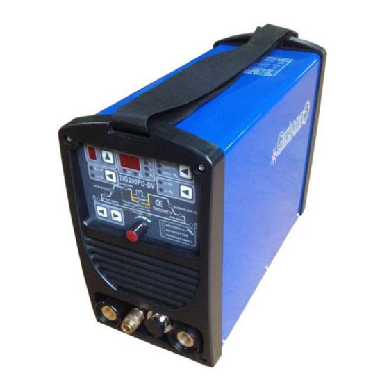
TIG200PD-DV
Operators's Manual
Safety, Setup and General Use Guide
REV.2 0 00135-16
Issue Date: May. 08, 2016
Manual No.: 0-1525
(Suitable for 1x110V or 1x220V)
EMPRESAS CARBONE S.A.
Calle 5ta. Rio Abajo, Panamá, Panamá
Telefonos: (507) 3916309 / 3916313
www.empresascarbone.com
IGBT INVERTER
DC TIG/PULSE TIG
WELDING MACHINE
Advertisement
Table of Contents

Related Manuals for CARBONE TIG200PD-DV


Summary of Contents for CARBONE TIG200PD-DV
- Page 1 DC TIG/PULSE TIG WELDING MACHINE (Suitable for 1x110V or 1x220V) Operators’s Manual Safety, Setup and General Use Guide EMPRESAS CARBONE S.A. REV.2 0 00135-16 Calle 5ta. Rio Abajo, Panamá, Panamá Issue Date: May. 08, 2016 Telefonos: (507) 3916309 / 3916313 Manual No.: 0-1525...
- Page 2 Dear Customer, Thank you for selecting the our machine. We appreciate you as a customer and hope that you will enjoy years of use from your welder. Please go directly to the our website to register your unit and receive your warranty information. Your unit registration is important should any information such as product updates or re-calls be issued.
- Page 3 Please record your equipment identification below for future reference. This information can be found on data plate at rear of machine. Product TIG200PD-DV : Serial No. ___________________________________ Date of Purchase _____________________________ Where Purchased _____________________________...
-
Page 4: Safety Precautions
SAFETY PRECAUTIONS We are dedicated to providing you with the best possible equipment and service to meet the demanding jobs that you have. We want to go beyond delivering a satisfactory product to you. That is the reason we offer technical support to assist you with your needs should an occasion occur. With proper use and care your product should deliver years of trouble free service. - Page 5 SAFETY PRECAUTIONS These safety precautions are for protection of safety and health. Failure to follow these guidelines may result in serious injury or death. Be careful to read and follow all cautions and warnings. Protect yourself and others. Welding and cutting processes produce high levels of ultraviolet (UV) radiation that can cause severe skin burn and damage.
- Page 6 SAFETY PRECAUTIONS WARNING! Persons with pacemakers should not weld, cut or be in the welding area until they consult with their physician. Some pacemakers are sensitive to EMF radiation and could severely malfunction while welding or while being in the vicinity of someone welding. Serious injury or death may occur! Welding and plasma cutting processes generate electro-magnetic fields and radiation.
- Page 7 SAFETY PRECAUTIONS WARNING! Electrical shock can kill. Make sure all electrical equipment is properly grounded. Do not use frayed, cut or otherwise damaged cables and leads. Do not stand, lean or rest on ground clamp. Do not stand in water or damp areas while weld-ing or cutting. Keep work surface dry.
-
Page 8: Table Of Contents
TABLE OF CONTENTS Page SAFETY PRECAUTIONS..........Installation.............Section A Technical Specifications..........A-1 Output Amps %duty cycle ..........A-2 Select Suitable Location..........A-3 Stacking ..............A-3 TRANSPORT - UNLOADING ..........A-3 Tilting...............A-3 Environmental Area ............A-3 Machine Grounding and High Frequency Interference Protection ..A-4 Input Connections ...........A-4 Reconnect Procedure............A-5 220/230/240V Input.............A-5... -
Page 9: Installation
INSTALLATION TECHNICAL SPECIFICATIONS max. rated Output Amps @% Duty Cycle (Based on a 10 minute cycle) (Example; 160A@60% for DC Stick and 200A@60% for DC TIG) Model TIG200PD-DV Power Supply Voltage 1x110V 50/60Hz 1x220V 50/60Hz Fuse rating No-load Voltage Rated Output Current... - Page 10 INSTALLATION Chart gives max. rated Output Amps @% Duty Cycle (Based on a 10 minute cycle) (Example; 160A@60% for DC Stick and 200A@60% for DC TIG) Using standard input cable for protected input supply 100% STICK(MMA) 220A OUTPUT AMPS Wiring and protection based on the IEC60974.1 National Electric Code: Use a Super Lag type fuse or circuit breaker with a delay in tripping action.
-
Page 11: Select Suitable Location
INSTALLATION SAFETY PRECAUTIONS Read entire installation section before starting installation. Neither let the equipment or the single unit fall, nor put it down with force. Once it has been removed from the packing, the ELECTRIC SHOCK can kill. power source can be used to move it in the ·Only qualified personnel should hand or on the shoulder. -
Page 12: Machine Grounding And High Frequency Interference Protection
INSTALLATION MACHINE GROUNDING AND HIGH following methods: FREQUENCY INTERFERENCE a) A metal underground water pipe in direct contact PROTECTION with the earth for ten feet or more. This welder must be grounded! See your local and b) A 3/4" (19mm) galvanized pipe or a 5/8" national electrical codes for proper grounding (16mm)solid galvanized iron, steel or copper rod methods. -
Page 13: Reconnect Procedure
INSTALLATION an individual branch circuit. Using fuses or circuit breakers smaller than 1Also called “inverse time” or “thermal/magnetic” recommended may result in "nuisance" shut-off circuit breakers. from welder inrush currents even if not welding at These circuit breakers have a delay in tripping action that decreases as the magnitude of the high currents. -
Page 14: Work Cable Connection
INSTALLATION ENGINE DRIVEN GENERATOR The Inverter machine can be operated on engine SHIELDING GAS CONNECTION driven generators as long as the 220/230/240 volt Obtain the necessary inert shielding gas (usually auxiliary meets the following conditions: argon). Connect the cylinder of gas with the . -
Page 15: Operation
OPERATION Read and understand this entire section before operating the machine. SAFETY PRECAUTIONS ELECTRIC SHOCK can kill. · Do not touch electrically live parts or electrode with skin or wet clothing. · Insulate yourself from work and ground. · Always wear dry insulating gloves. Read and follow "Electric Shock Warnings"... -
Page 16: Product Description
OPERATION PRODUCT DESCRIPTION RECOMMENDED QUIPMENT/INTERFACE The Precision TIG is a member of our field (See Installed Options in Accessories Section for acclaimed Precision TIG family of industrial arc more details) welding power sources. Premium features include: The Precision TIG will be available as a basic 1 Precise constant current output. - Page 17 OPERATION CONTROLS AND SETTINGS All operator controls and adjustments are located on the case front of the TIG machine. Refer to Figure B.1 and the corresponding explanations. FIGURE B.1 CONTROL PANEL 1. FRONT PANEL 2. BACK PANEL 1.Memory chanel LED 2.
- Page 18 OPERATION equipment is located nearby. See page 24 for 2. Data Display - The unit features a single main instructions on proper starting techniques. digital display. The data in the display is always 12. 2 T/ 4 T slector accompanied by a corresponding LED light which After the arc is started the output current will be indicates the function being represented.
- Page 19 OPERATION After the arc is started the output current will be at the Start current. This condition can be maintained (4 step diagram 2) as long or as short as necessary. If the Start current is not necessary, do not hold the TIG torch trigger as described at the beginning of this step.
- Page 20 OPERATION 19.nameplate 21.argon inlet connected gas pipe of flow meter he data plate stamped on the metal structure 22.power supply complies with 60974-1, EN50199(EN60974-10) international standards and connected main supply contains the following information: 23. safety earthing column The earthing must be made according to the national regulations.
-
Page 21: Operating Steps
OPERATION OPERATING STEPS WELDING IN TIG MODE 1 Connect the TIG torch and cable Twist-Mate quick connect plug to the Electrode/Gas output receptacle. This receptacle also contains an integral gas connection for the torch. Connect the work clamp to the work piece. 2 Set the Pulse on /pulse off/MMA slector to "... -
Page 22: Dc Pulsed Tig
OPERATION Increasing frequency constricts arc, increases stability and improves weld quality. FIGURE B.6 I(A) DC TIG-NOT PULSED I(A) DC PULSED TIG STEEL TIG WELDING The TIG process is very effective for welding both carbon steel alloy steel, especially applications requiring precision results. -
Page 23: Gtaw Process
OPERATION · GTAW Process Approximate Argon Electrode Polarity Electrode Tip Sharpened Gas Flow Rate Preparation Electrode Type EWTh-1, EWLa-1 C.F.H. (l/min.) EWTh-2, EWCE-2 Electrode Stainless Aluminum Size-in. (mm) Steel .010 (0.25) Up to 15 A. 3-8 (2-4) 3-8 (2-4) .020 (0.50) Up to 15 A. -
Page 24: Dc Tig Welding Quick Start Up
B-10 OPERATION B-10 DC TIG WELDING QUICK START UP the relaxed position, with no thumb pressure. "Maximum" refers to a fully depressed Foot ELECTRIC SHOCK can kill. Ampcontrol,or a fully extended Hand Ampcontrol. . Have an electrician install When the welder is in TIG modes activating the and service this equipment. - Page 25 B-11 OPERATION B-11...
- Page 26 B-12 OPERATION B-12...
-
Page 27: Welding In Stick Mode
B-13 OPERATION B-13 WELDING IN STICK MODE will be electrically hot whenever the power 1 Put the electrode holder and cable quick connect switch is turned on. plug into the electrode output receptacle. Turn clockwise until tight. Connect the work clamp to the 5 Turn the power switch to "ON". - Page 28 B-14 OPERATION B-14 1. Turn on the power switch on the rear of the unit. Allow unit to cycle through its start up program. 2. Select the Stick mode with the Pulse on /pulse off/MMA selector switch. 3. Make sure electrode holder is connected to the positive terminal and the work clamp is connected to the negative connector.
-
Page 29: Maintenance
MAINTENANCE 7 SPARK GAP ADJUSTMENT SAFETY PRECAUTIONS The spark gap .020(.5mm) is set at the factory to a gap of 0.015 inches (0.4mm) See Figure D.1. This setting is adequate for most applications. Where ELECTRIC SHOCK can kill. ● Only qualified personnel less high frequency is desired, the setting can be should per-form this reduced to 0.015 inches (0.4mm). -
Page 30: Troubleshooting
TROUBLESHOOTING HOW TO USE TROUBLESHOOTING GUIDE Service and Repair should only be performed by our Factory Trained Personnel. Unauthorized repairs performed on this equipment may result in danger to the technician and machine operator and will invalidate your factory warranty. For your safety and to avoid Electrical Shock, please observe all safety notes and precautions detailed throughout this manual. - Page 31 TROUBLESHOOTING Observe all Safety Guidelines detailed throughout this manual OUTPUT PROBLEMS POSSIBLE AREAS OF RECOMMENDED PROBLEMS (SYMPTOMS) MISADJUSTMENTS COURSE OF ACTION 1. Make certain that the input power switch is in the "ON" position and machine is plugged in. 2. Check the input voltage at the Machine is Dead -No Output machine.
- Page 32 TROUBLESHOOTING Observe all Safety Guidelines detailed throughout this manual TIG MODE PROBLEMS POSSIBLE AREAS OF RECOMMENDED COURSE PROBLEMS (SYMPTOMS) MISADJUSTMENTS(S) OF ACTION 1. Problem may be caused by high frequency interference. Make sure that the machine is grounded properly according to the installation Machine output instructions.
- Page 33 TROUBLESHOOTING Observe all Safety Guidelines detailed throughout this manual TIG MODE PROBLEMS POSSIBLE AREAS OF RECOMMENDED COURSE PROBLEMS (SYMPTOMS) MISADJUSTMENTS(S) OF ACTION 1. Clean any oily or organic contamination from the work piece. 2. Tungsten electrode may be contaminated. Replace or sharpen. Black areas along weld 3.Check for contaminated gas or leaks in bead...
- Page 34 TROUBLESHOOTING Observe all Safety Guidelines detailed throughout this manual TIG WELD PROBLEMS POSSIBLE AREAS OF RECOMMENDED COURSE PROBLEMS (SYMPTOMS) MISADJUSTMENTS(S) OF ACTION 1. If the machine location is in a highly No high frequency. Machine dirty environment with conductive is in the TIG Mode and has contaminants, check and clean the spark normal output.
- Page 35 TROUBLESHOOTING Observe all Safety Guidelines detailed throughout this manual STICK WELDING PROBLEMS POSSIBLE AREAS OF RECOMMENDED COURSE PROBLEMS (SYMPTOMS) MISADJUSTMENTS(S) OF ACTION Weld current may be set too high for electrode size. Reduce current control setting, or use a larger Stick electrode "Blasts Off"...
- Page 36 DIAGRAMS Diagram for the machine working elements. NOTE: This diagram is for reference only. It may not be accurate for all machines covered by this manual. If the diagram is illegible, write to the Service Department for a replacement. Give the equipment code number.
-
Page 37: Accessories
Adjustable foot control Operation instructions Certificate of quality ━━━━━━━━━━━━━━━━━━━━━━━ Certificate of quality Name of product: PULSE TIG WELDING Type of product: TIG200PD-DV Packing Test results of this welder fulfils_____________ _________technical requirements and its release from the works is granted. Inspector_________ Date___________... - Page 38 Do not touch electrically live parts or Keep flammable materials away. Wear eye, ear and body protection. WARNING electrode with skin or wet clothing. Insulate yourself from work and ground. Spanish No toque las partes o los electrodos Mantenga el material combustible Protéjase los ojos, los oídos y el AVISO DE bajo carga con la piel o ropa moja-...
- Page 39 Keep your head out of fumes. Turn power off before servicing. Do not operate with panel open or Use ventilation or exhaust to guards off. WARNING remove fumes from breathing zone. Spanish Los humos fuera de la zona de res- Desconectar el cable de ali- No operar con panel abierto o AVISO DE...
Need help?
Do you have a question about the TIG200PD-DV and is the answer not in the manual?
Questions and answers