Table of Contents

Related Manuals for KINNEY KD Series


Summary of Contents for KINNEY KD Series
- Page 1 Kinney ® Single-Stage Duplex Rotary Piston Pump Manual 1808 Rev B p/n 001808 0000 WARNING: Do Not Operate Before Reading Manual KD Series OPERATOR’S MANUAL Models KD-30 KD-50 800.825.6937 | www.kinneyvacuum.com Original Instructions...
- Page 2 No part of this publication may be reproduced or used in any form by any means - graphic, electronic or mechanical, including photocopying, recording, taping or information storage and retrieval systems - without the written permission of Kinney ® Product information and specifications subject to change.
-
Page 3: Table Of Contents
Table of Contents Table of Contents Introduction .................. 1 Applicable Documentation ..............1 Scope of Manual ................... 1 Conventions, Safety and Data Plate ........... 2 Graphic Conventions Used in this Manual ..........2 Safety Instruction Tags ................2 Safety Precautions for Rotary Piston Pumps ......... 3 Data Plate .................... - Page 4 Table of Contents Pre-Start Checks ................. 12 Starting ....................12 Stopping ....................13 Gas Ballast ..................13 Maintenance ................14 General ....................14 Changing Oil ..................14 V-Belts ....................14 Gear Drive Units .................. 14 Draining and Refilling Oil ..............14 Bearing Lubrication ................
-
Page 5: Introduction
SCOPE OF MANUAL KINNEY KD vacuum pumps are built to exacting standards and, if properly installed and maintained, The scope of this manual includes the following will provide many years of reliable service. Read... -
Page 6: Conventions, Safety And Data Plate
CONVENTIONS, SAFETY AND DATA PLATE GRAPHIC CONVENTIONS USED IN OTE: Indicates a procedure, practice, or condition that should be followed in THIS MANUAL order for the equipment to function in the manner intended. The following hazard levels are referenced within this manual: SAFETY INSTRUCTION TAGS DANGER... -
Page 7: Safety Precautions For Rotary Piston Pumps
Conventions, Safety and Data Plate SAFETY PRECAUTIONS FOR • Accidental starting or operation of the pump while maintenance is in progress may cause ROTARY PISTON PUMPS injury or damage. • Lift only with the lifting eyebolts supplied with Please read the following safety information before the pump. -
Page 8: Data Plate
This manual describes instructions and precautions CAUTION to be observed in the handling and maintenance of Kinney KD Rotary Piston Vacuum Pumps. It is Hearing protection is required strongly recommended that those who operate or while the pump is in operation. -
Page 9: Lifting
LIFTING WARNING The vacuum pump must be handled using an appropriate device such as a fork truck Table 4-2 or appropriate lifting device. See on page 7 for approximate weights. Care should be taken to assure pump does not overturn during handling and installation. Manual 1808 Rev B p/n 001808 0000... -
Page 10: Description
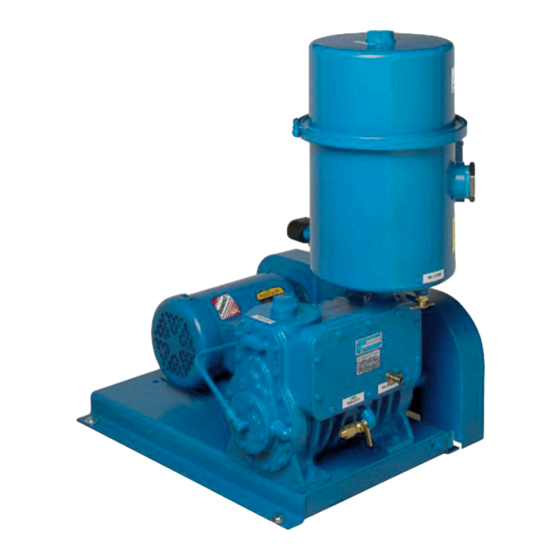
DESCRIPTION GENERAL PUMP COMPONENTS The visual difference between the two pumps is All components are easily serviced and no special in the oil separators. Internally, the pistons, cams, tools are required. The reliable, leak-free shaft seal and slide pins of the KD-50 are treated to be able requires no adjustment or maintenance. - Page 11 KD-30 DIRECT KD-50 BELT KD-50 DIRECT DRIVE DRIVE DRIVE DRIVE Oil Capacity (Kinney AX) 4 qt (3.8 L) 4 qt (3.8 L) 12 qt (11.4 L) 12 qt (11.4 L) Weight Complete Pump 200 lb (91 kg) 650 lb (295 kg)
-
Page 12: Operating Cycle
Description SEALING AND LUBRICATING Each rotary piston is composed of a cylindrical element that encloses the shaft and a hollow rectangular extension that moves through a slide The oil flows through the pump by means of pin. The piston slide pin has openings that are differential pressure between atmosphere and the covered and uncovered as it passes through the pump inlet, and it is drawn into the pump at each... -
Page 13: Installation
INSTALLATION GENERAL Select a pump site with enough room for pump maintenance and service. Secure the pump to a level, rigid, support. Spring vibramounts can be used if sufficiently flexible connectors are used in the manifolding. V-BELT DRIVE Figure 5-1 – V-Belt Tensioning To install the V-belts, loosen the motor mounting screws and slide the motor toward the pump. -
Page 14: Direct Drive
This includes, at a minimum, the ability to access oil fill and drain locations and to view the oil level sight glass. The KD series Drive-Drive models are direct driven by two methods: • 8 pole (KD50) or 12 pole (KD30) motors •... -
Page 15: Vacuum Gauges
Loctite 567 is to any electric component of the unit. available from Kinney as a compound for thread sizes up to 1 in. (2.5 cm) in diameter or Titeseal Check the operating voltage of the motor... -
Page 16: Operation
OPERATION PRE-START CHECKS WARNING Performed the following pre-start checks if The belt guard must be properly secured maximum pumping conditions are required. to the pump at all times while the pump is running. 1. Check that the suction lines are tight and When operating the pump in an enclosed absolutely free of all foreign matter. -
Page 17: Stopping
Operation The oil level will change with the pumping In addition to preventing vapor condensation, pressure. When the pump is first started, the oil will the use of gas ballast also reduces discharge rise. As the inlet pressure is reduced, the oil level valve noise to a low level. -
Page 18: Maintenance
MAINTENANCE GENERAL V-BELTS Check the oil level daily for the first week of To change the V-belt, loosen the motor mounting operation and weekly thereafter. The oil level screws and slide the motor toward the pump until should be about midway on the sight gauge when the old belt can easily be slipped from the pulleys. -
Page 19: Bearing Lubrication
Maintenance OIL SEPARATOR Oil Plugs / Ventilator 1. Prior to removing plugs, ensure that the pump All KD-30 and KD-50 blowers built since October has cooled sufficiently so that oil will not burn. 1984 are fitted with oil mist eliminators in the oil separator. - Page 20 Maintenance Figure 7-1 – Return Line One of the following two areas can be selected for the oil to return to the pump when operating above 5 Torr: • If the pump operating range is between 5 and 150 Torr, the returning oil should enter the pump through the gas ballast valve, in which case the valve must be left open.
-
Page 21: Disassembly / Assembly
DISASSEMBLY / ASSEMBLY DISASSEMBLY 10. Remove the closed head, piston, slide pin, and cam. Remove the cam by tapping the shaft with a soft-faced hammer until the cam is free Disassemble the pump only to the extent from the shaft. Disassemble only if cam and necessary to repair it. - Page 22 Disassembly / Assembly 4. Position the closed head piston with the inlet 10. Install the discharge valves and replace the ports of the piston slide facing away from the cylinder cover and gasket. discharge valve side of the pump. Place the 11.
-
Page 23: Troubleshooting
TROUBLESHOOTING STARTING TROUBLES OR CHECKING PUMP PERFORMANCE STALLING If the processing time increases or the ultimate pressure becomes poor with no recent changes Pump starting troubles or stalling may be due in the process or in system configuration, test the to loose or broken belts, lack of lubrication, pump to determine if the trouble is in the pump obstruction inside the pump, temperature too low,... -
Page 24: Pump Leaks
Loctite 2. Detect large leaks by pressurizing the pump 515 is available from Kinney to permanently seal and painting with a soap solution. Bubbles will the leaks once they have been found. If leaks indicate leaks. -
Page 25: Oil Contamination
Troubleshooting OIL CONTAMINATION DISCHARGE VALVES When the pressure has been satisfactory for When the cause of poor pump performance is some time and then the pressure gradually not due to leaks or oil contamination, inspect increases, this indicates oil contamination. When the discharge valves. -
Page 26: Shaft Seal
Troubleshooting When the pump is operating without gas ballast, Under normal conditions, the shaft seal shown a sharp clicking noise generally indicates proper in Figure 9-2 on page 22 has a long, trouble- valve closing. To gain access to the valves, drain free life. - Page 27 Troubleshooting SYMPTOM PROBABLE CAUSE REMEDIES System ultimate pressure System contaminated Clean equipment with acetone, alcohol, or ether. excessively high by volatile material Oil is contaminated Pump down using full gas ballast overnight. Process equipment leaks, vacuum pump Check leaks. leaks Oil flow blocked Clean oil lines.
- Page 28 Troubleshooting SYMPTOM PROBABLE CAUSE REMEDIES Output shaft does not Drive between shafts rotate, even though the interrupted in the gear Return the gear unit/geared motor for repair. motor is running or the unit input shaft is rotating A meshing or grinding sound: damage to bearings Unusual, regular running...
-
Page 29: Replacement Parts
REPLACEMENT PARTS GENERAL The graphics on the following pages and their parts lists cover all parts in the KD-30 and KD-50 pumps, any of which are available as spare parts. Always include the model and serial number of the pump when ordering parts. -
Page 30: Kd-30A Exploded View Drawing
Replacement Parts KD-30A EXPLODED VIEW DRAWING Manual 1808 Rev B p/n 001808 0000... -
Page 31: Kd-30A Parts List
Replacement Parts KD-30A PARTS LIST ITEM ITEM DESCRIPTION DESCRIPTION Gas Ballast Valve Cylinder Drain Cock, Oil, 1/4 NPT Head, Open & Closed End Drain Cock, Oil, 3/8 NPT Housing, Shaft Seal & Street Elbow, 3/8 NPT Bearing Coupling, 3/8 NPT Cap, Closed End Oil Mist Eliminator Cover, Cylinder... -
Page 32: Kd-50B Exploded View Drawing
Replacement Parts KD-50B EXPLODED VIEW DRAWING Manual 1808 Rev B p/n 001808 0000... -
Page 33: Kd-50B Parts List
Replacement Parts KD-50B PARTS LIST ITEM ITEM DESCRIPTION DESCRIPTION Gas Ballast Valve Cylinder Drain Cock, Oil, 1/4 NPT Head, Open & Closed End Discharge Separator Tank Housing, Shaft Seal & Assy. Bearing 31A** Flange Gasket Cap, Closed End Oil Mist Eliminator Element Cover, Cylinder 31D** Check Disc, Viton... -
Page 34: Declaration Of Incorporation
Page Intentionally Blank... -
Page 35: Warranty - Vacuum Products
WARRANTY – VACUUM PRODUCTS Subject to the terms and conditions hereinafter set forth and set forth in General Terms of Sale, Kinney (the Seller) warrants products and parts of its manufacture, when shipped, and its work (including installation and start-up) when performed, will be of good quality and will be free from defects in material and workmanship. - Page 36 Page Intentionally Blank...
-
Page 37: Operating Data Form / Product Registration
NOTES: IMPORTANT All vacuum boosters and vacuum pumps manufactured by Kinney are date coded at time of shipment. In order to assure you of the full benefits of the product warranty, please complete, tear out and return the product registration card. You may also register your product online at www.kinneyvacuum.com or contact... - Page 38 For Service & Repair, Technical Support, or Product Sales contact: Kinney VACUUM & BLOWER SYSTEMS 4840 West Kearney Street TUTHILL CORPORATION Springfield, Missouri USA 65803-8702 O 417.865.8715 800.825.6937 F 417.865.2950 www.kinneyvacuum.com Manual 1808 Rev B p/n 001808 0000 04/21...
Need help?
Do you have a question about the KD Series and is the answer not in the manual?
Questions and answers