Table of Contents
Advertisement
Quick Links
Advertisement
Table of Contents

Related Manuals for KINNEY KVC Series


Summary of Contents for KINNEY KVC Series
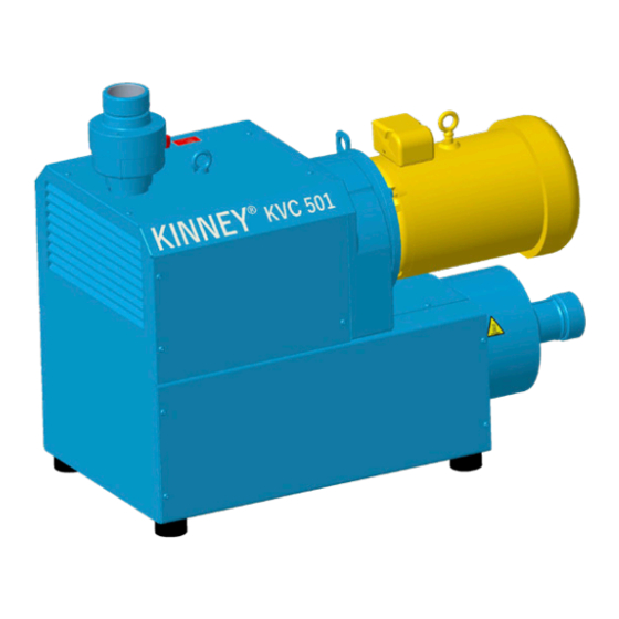
- Page 1 Kinney ® Dry Claw Vacuum Pumps Manual 1866 Rev A p/n 1866 WARNING: Do Not Operate Before Reading Manual KVC Series OPERATOR’S MANUAL Models KVC-60 KVC-100 KVC-150 KVC-251 KVC-301 KVC-401 KVC-501 KVC-1000 800.825.6937 | www.kinneyvacuum.com Original Instructions...
- Page 2 No part of this publication may be reproduced or used in any form by any means - graphic, electronic or mechanical, including photocopying, recording, taping or information storage and retrieval systems - without the written permission of Kinney ® Product information and specifications subject to change.
-
Page 3: Table Of Contents
Table of Contents Table of Contents Introduction .................. 1 Conventions and Data Plate ............2 Graphic Conventions Used in this Manual ..........2 Lifting .................... 5 Lifting Configuration ................5 Description ................... 6 Designated Use ..................6 Unacceptable Operating Modes ............6 Specifications .................. - Page 4 Table of Contents Connecting the Motor ................. 14 Power Supply ................14 Operation ..................15 Checking Rotor Rotation Direction ............15 Maintenance ................16 Ensuring Operational Safety ............... 16 Maintenance Interval Schedule ............17 Changing the Oil ................. 17 Oil Diagrams ..................18 KVC-60 Oil Diagram ..............
-
Page 5: Introduction
SCOPE OF MANUAL Kinney KVC Series vacuum pumps are built to exacting standards and, if properly installed The scope of this manual includes the KVC Series and maintained, will provide many years of dry claw vacuum pumps. reliable service. Read and follow every step of these instructions when installing and maintaining the pump. -
Page 6: Conventions And Data Plate
CONVENTIONS AND DATA PLATE GRAPHIC CONVENTIONS IN THIS order for the equipment to function in the manner intended. MANUAL CAUTION The following are hazard levels referenced within this manual: Read manual before operation or bodily harm may result. DANGER Attention should be given to the safety related sections of this Indicates a hazardous situation that, if not manual. - Page 7 Conventions and Data Plate CAUTION Hearing protection is required while the pump is in operation. At ultimate pressure noise levels are 80 dBA at 60 Hz, however due to process or installation conditions noise levels may be higher. CAUTION Do not touch hot surfaces. Do not touch the vacuum pump while it is in operation and assure that the pump is cool...
- Page 8 Maximum RPM at which the pump can be operated This manual describes instructions and precautions to be observed in the handling and maintenance of Kinney KVC Series dry claw vacuum pumps. ® It is strongly recommended that those who operate or maintain the pump read this manual carefully prior to pump operation, to ensure personal safety and pump life.
-
Page 9: Lifting
WARNING Refer to Figure 3-1 – Lifting Configuration for The vacuum pump must be handled using further details on how to properly lift KVC Series an appropriate device such as a fork truck vacuum pump. or appropriate lifting device. See Table 4-1 on page 7 for approximate weights. -
Page 10: Description
The synchronous gears and the bearings on the motor side are lubricated with oil. These The KVC Series is driven by an IEC (KVC60 only) components are in a gearbox that also contains and NEMA flanged three phase motors via a the oil supply. -
Page 11: Specifications
Operation SPECIFICATIONS UNIT KVC-60 KVC-100 KVC-150 KVC-251 KVC-301 KVC-401 KVC-501 KVC-1000 Nominal 42.4 70.6 Displacement (72) (120) (80) (255) (350) (485) (603) (1140) Motor Power Rotation 3485 3450 3450 3450 3550 3550 3550 3550 Speed Oil Capacity U.S. gal (Total/Refill) (.4) (.55) (.6) -
Page 12: Kvc-60 Feature Setup
Description KVC-60 FEATURE SETUP Vacuum connection Oil recommendation plate Exhaust air outlet Data plate Vacuum regulating valve Direction of rotation arrow Cooling air inlet Drive motor Cooling air outlet Motor data plate Oil filling point hot surfaces > 70 °C Oil sight glass Mesh filter Oil discharge point... -
Page 13: Kvc-100 / Kvc-150 / Kvc-251 Feature Setup
Operation KVC-100 / KVC-150 / KVC-251 FEATURE SETUP Vacuum connection Oil recommendation plate Exhaust air outlet Data plate Vacuum Regulating valve Rotation direction plate Cooling air inlet Drive motor Cooling air outlet Motor data plate Oil filling point hot surfaces > 70 °C Oil sight glass Junction box Oil discharge point... -
Page 14: Kvc-301 / Kvc-401 / Kvc-501 / Kvc-1000 Feature Setup
Description KVC-301 / KVC-401 / KVC-501 / KVC-1000 FEATURE SETUP Vacuum connection Oil discharge point Air outlet connection Oil recommendation plate Exhaust silencer Data plate Condensate drain (only with “XD”) Direction of rotation arrow Cooling air inlet Drive motor Cooling air outlet Motor data plate Oil filling point hot surfaces >... - Page 15 Operation Manual 1866 Rev A p/n 1866...
-
Page 16: Installation
INSTALLATION SAFETY WARNING Use lockout / tagout procedures to disable the electrical energy source before any service or DANGER work is done on the vacuum pumps. Internal and external rotating parts of the pump and driving CAUTION equipment can produce serious physical injuries. -
Page 17: Filling The Pump With Oil
Kinney directly for guidance. VACUUM CONNECTION FILLING THE PUMP WITH OIL Use oil recommended by Kinney and see the The pumping capacity of the vacuum pump is specifications for the quantity of oil required to fill reduced if the suction pipe is too narrow and/or long. -
Page 18: Length Of Connection Pipes
Exhaust Air Must Not be Restricted strain relief. Kinney recommends using motor protection switches with delayed switch off, Do not block the exhaust pipe of the pump depending on possible excess current. -
Page 19: Operation
OPERATION WARNING Wait until the machine stops. The machine Improper use may lead to severe or fatal injuries. must only be switched on again after it stops. Therefore be sure to obey the safety instructions. CHECKING ROTOR CAUTION ROTATION DIRECTION Hot surfaces. -
Page 20: Maintenance
MAINTENANCE ENSURING OPERATIONAL SAFETY DANGER Danger of death from touching live parts. Before maintenance work disconnect the machine by pressing the main switch or unplugging it and ensure it cannot be turned on again. WARNING Hot surfaces and equipment. During maintenance work there is the danger of getting burnt on hot components and by machine lubricating oil. -
Page 21: Maintenance Interval Schedule
5,000 – 20,000 Hours KVC-301 – KVC-501: 20,000 Hours KVC-1000: 8,000 Hours Monthly / Every 6 Months KVC Series: Clean or replace filter cartridge. Dependent Discharged Media Cleanliness KVC-100 – KVC-251: Clean micro filter. Yearly (at least once yearly) Check for coupling wear. -
Page 22: Oil Diagrams
Maintenance KVC SERIES OIL DIAGRAMS KVC-301 / KVC-401 / KVC-501 / KVC-1000 Oil Diagram KVC-60 Oil Diagram Oil filling point Oil filling point Oil sight glass Oil sight glass Oil discharge point Oil discharge point Oil recommendation plate Oil recommendation plate... -
Page 23: Filter Cleaning
Undo the screws on the housing flange. Remove The filter cartridge (KVC Series) for the suction the motor axially with half of the coupling on the filter must be cleaned monthly or more often motor side and suspend with a lifting device. -
Page 24: Troubleshooting
TROUBLESHOOTING Although Kinney vacuum pumps are well-designed and manufactured, problems may occur due to normal wear and the need for readjustment. The following chart lists symptoms that may occur along with probable causes and remedies. SYMPTOM PROBABLE CAUSE REMEDIES Mains voltage/frequency does not correspond... -
Page 25: Part Number Designations
Troubleshooting PART NUMBER DESIGNATIONS Position 4: MOTOR HP EXAMPLE: MODEL KVC60CD-BDD Positon 4 Position #: 7.5hp 10hp Position 1 12hp PUMP MODEL NUMBER: 15hp 30hp Position 1 KVC-60 Position 5: KVC-100 MOTOR SUPPLIED KVC-150 KVC-251 Position 5 SIZE KVC-301 NEMA VOLTAGES KVC-401 3/50-60/190/380//230/460... -
Page 26: Exploded Views And Parts Lists
Exploded Views and Parts Lists KVC-60 SERIES EXPLODED VIEW DRAWING Wearing Parts Seals Repair kits available consisting of V- and D- parts Manual 1866 Rev A p/n 1866... - Page 27 Exploded Views and Parts Lists KVC-60 SERIES PARTS LIST ITEM PART ITEM PART DESCRIPTION DESCRIPTION TYPE TYPE Compressor parts Silencer Rotor 1 Silencer Rotor 2 Gasket Spacer bushing Setscrew Housing cover B Shim Shaft, driving Hexhead nut Shaft, driven Assembly parts suction side Cylinder Gasket Conical-clamping element...
- Page 28 Exploded Views and Parts Lists KVC-100 SERIES EXPLODED VIEW DRAWING Wearing Parts Seals Repair kits available consisting of V- and D- parts Manual 1866 Rev A p/n 1866...
- Page 29 Exploded Views and Parts Lists KVC-100 SERIES PARTS LIST ITEM PART ITEM PART DESCRIPTION DESCRIPTION TYPE TYPE Compressor housing Covering cap Cover panel Rotor 1 Front cover Rotor 2 Bottom plate Base rail, left End cover Base rail, right O-Ring Vibration absorber Spacer ring Gear...
- Page 30 Exploded Views and Parts Lists KVC-150 SERIES EXPLODED VIEW DRAWING Wearing Parts Seals Repair kits available consisting of V- and D- parts Manual 1866 Rev A p/n 1866...
- Page 31 Exploded Views and Parts Lists KVC-150 SERIES PARTS LIST ITEM PART ITEM PART DESCRIPTION DESCRIPTION TYPE TYPE Compressor parts Motor flange, part 2 Housing Cover B Covering cap Compressor housing Cover Disc Front cover Rotor 1 Bottom plate Rotor 2 Rubber foot O-Ring Hexhead nut...
- Page 32 Exploded Views and Parts Lists KVC-251 SERIES EXPLODED VIEW DRAWING Wearing Parts Seals Repair kits available consisting of V- and D- parts Manual 1866 Rev A p/n 1866...
- Page 33 Exploded Views and Parts Lists KVC-251 SERIES PARTS LIST ITEM PART ITEM PART DESCRIPTION DESCRIPTION TYPE TYPE Motor flange, part 2 Compressor parts Housing Cover B Covering cap Compressor housing Cover Disc Front cover Rotor 1 Base plate, cpl. Rotor 2 Rubber foot O-Ring Hexhead nut...
- Page 34 Exploded Views and Parts Lists KVC-301 SERIES EXPLODED VIEW DRAWING Wearing Parts Seals Repair kits available consisting of V- and D- parts Manual 1866 Rev A p/n 1866...
- Page 35 Exploded Views and Parts Lists KVC-301 SERIES PARTS LIST ITEM PART ITEM PART DESCRIPTION DESCRIPTION TYPE TYPE Accoustic mat Compressor parts Housing Cover B Cover with insulation mat Rotor 1, driving Front cover Rotor 2, driven Cover plate Conical-clamping element Hexhead nut Disc Parts on suction side...
- Page 36 Exploded Views and Parts Lists KVC-401-501 SERIES EXPLODED VIEW DRAWING Wearing Parts Seals Repair kits available consisting of V- and D- parts Manual 1866 Rev A p/n 1866...
- Page 37 Exploded Views and Parts Lists KVC-401-501 SERIES PARTS LIST ITEM PART ITEM PART DESCRIPTION DESCRIPTION TYPE TYPE Compressor parts Cover Housing Cover B Basis foot Rotor 1, driving Rubber foot Rotor 2, driven Edge protection section Conical-clamping element Edge protection section Pressing cylinder, KVC 401 Intermediate sheet with insulation mat Spacer ring...
- Page 38 Exploded Views and Parts Lists KVC-1000 SERIES EXPLODED VIEW DRAWING Wearing Parts Seals Repair kits available consisting of V- and D- parts Manual 1866 Rev A p/n 1866...
- Page 39 Exploded Views and Parts Lists KVC-1000 SERIES PARTS LIST ITEM PART ITEM PART DESCRIPTION DESCRIPTION TYPE TYPE Compressor parts 54.1 Bottom plate cpl. Housing Cover B 54.2 Top cover cpl. Rotor 1, driving 54.3 Front cover cpl. Rotor 2, driven 54.4 Back cover Conical-clamping element...
-
Page 40: Replacement Kits
Exploded Views and Parts Lists REPLACEMENT KITS AVAILABLE AFTERMARKET OIL, GEAR, KV 150, QUART OIL, GEAR, KV 150, 5 GALLON REBUILD KIT, KVC 100 REBUILD KIT, KVC 150 REBUILD KIT, KVC 60 REBUILD KIT, KVC 301 REBUILD KIT, KVC 401 REBUILD KIT, KVC 501 REBUILD KIT, KVC 1000 REBUILD KIT, KVC 251... - Page 41 Exploded Views and Parts Lists Manual 1866 Rev A p/n 1866...
-
Page 42: Warranty - Vacuum Products
WARRANTY – VACUUM PRODUCTS Subject to the terms and conditions hereinafter set forth and set forth in General Terms of Sale, Kinney (the Seller) warrants products and parts of its manufacture, when shipped, and its work (including installation and start-up) when performed, will be of good quality and will be free from defects in material and workmanship. -
Page 43: Operating Data Form / Product Registration
NOTES: IMPORTANT All vacuum boosters and vacuum pumps manufactured by Kinney are date coded at time of shipment. In order to assure you of the full benefits of the product warranty, please complete, tear out and return the product registration card. You may also register your product online at www.kinneyvacuum.com or contact... - Page 44 For Service & Repair, Technical Support, or Product Sales contact: Kinney 4840 West Kearney Street Springfield, Missouri USA 65803-8702 O 417.865.8715 800.825.6937 F 417.865.2950 Manual 1866 Rev A p/n 1866 www.kinneyvacuum.com 09/21...
Need help?
Do you have a question about the KVC Series and is the answer not in the manual?
Questions and answers