Table of Contents
Advertisement
Advertisement
Table of Contents

Related Manuals for KINNEY KVO Series


Summary of Contents for KINNEY KVO Series
- Page 1 Kinney ® Oil Sealed Rotary Vane Vacuum Pumps Manual 1867 Rev A p/n 1867 WARNING: Do Not Operate Before Reading Manual KVO Series OPERATOR’S MANUAL Models KVO-50 KVO-75 KVO-150 KVO-200 KVO-300 KVO-400 KVO-500 KVO-700 KVO-900 KVO-1100 KVO-1300 800.825.6937 | www.kinneyvacuum.com...
- Page 2 No part of this publication may be reproduced or used in any form by any means - graphic, electronic or mechanical, including photocopying, recording, taping or information storage and retrieval systems - without the written permission of Kinney ® Product information and specifications subject to change.
-
Page 3: Table Of Contents
Table of Contents Table of Contents Introduction .................. 1 Conventions and Data Plate ............2 Graphic Conventions Used in this Manual ..........2 Lifting .................... 5 Lifting Configuration ................5 Description ................... 6 Designated Use ..................6 Unacceptable Operating Modes ............7 Specifications .................. - Page 4 Table of Contents Connecting the Motor ................. 13 Power Supply ................13 Operation ..................14 Checking Rotor Rotation Direction ............14 Maintenance ................15 Ensuring Operational Safety ............... 15 Maintenance Interval Schedule ............16 Changing the Oil ................. 16 Oil Removal ..................16 KVO-50 –...
-
Page 5: Introduction
SCOPE OF MANUAL Kinney KVO Series vacuum pumps are built to The scope of this manual includes the KVO Series exacting standards and, if properly installed oil sealed rotary vane vacuum pumps. and maintained, will provide many years of reliable service. -
Page 6: Conventions And Data Plate
CONVENTIONS AND DATA PLATE GRAPHIC CONVENTIONS IN THIS order for the equipment to function in the manner intended. MANUAL CAUTION The following are hazard levels referenced within this manual: Read manual before operation or bodily harm may result. DANGER Attention should be given to the safety related sections of this Indicates a hazardous situation that, if not manual. - Page 7 Conventions and Data Plate CAUTION Hearing protection is required while the pump is in operation. At ultimate pressure noise levels are 80 dBA at 60 Hz, however due to process or installation conditions noise levels may be higher. CAUTION Do not touch hot surfaces. Do not touch the vacuum pump while it is in operation and assure that the pump is cool...
- Page 8 Maximum RPM at which the pump can be operated This manual describes instructions and precautions to be observed in the handling and maintenance of Kinney KVO Series oil sealed rotary vane ® vacuum pumps. It is strongly recommended that those who operate or maintain the pump read this manual carefully prior to pump operation, to ensure personal safety and pump life.
-
Page 9: Lifting
WARNING Refer to Figure 3-1 – Lifting Configuration for The vacuum pump must be handled using further details on how to properly lift KVO Series an appropriate device such as a fork truck vacuum pump. or appropriate lifting device. See Table 4-1 on page 7 for approximate weights. -
Page 10: Description
DESCRIPTION The KVO vane vacuum pumps are single-stage oil DESIGNATED USE flooded rotary vane vacuum pumps. The rotary vane divides the pump housing into several chambers The machine must only be operated in such areas whose volumes change periodically. The oil ensures as are described in the operating instructions: for the sealing of the gap, an optimum lubrication and the dissipation of the compression heat. -
Page 11: Unacceptable Operating Modes
Operation UNACCEPTABLE OPERATING MODES • Using the machine in non-commercial plants • Extracting, conveying, and compressing if the necessary precautions and protective explosive, inflammable, aggressive or poisonous measures have not been taken in the plant media, e.g. dust as per ATEX zone 20-22, solvents or gaseous oxygen and other oxidants •... -
Page 12: Kvo-50 / Kvo-75 / Kvo-100 / Kvo-150 Feature Setup
Description KVO-50 / KVO-75 / KVO-100 / KVO-150 FEATURE SETUP Vacuum connection Oil recommendation plate Exhaust air outlet Data plate Suction flange Rotation direction arrow Cooling air inlet Drive motor Cooling air outlet Motor data plate Oil filling point Hot surfaces > 70 °C Oil sight glass Oil remover housing Oil discharge point... -
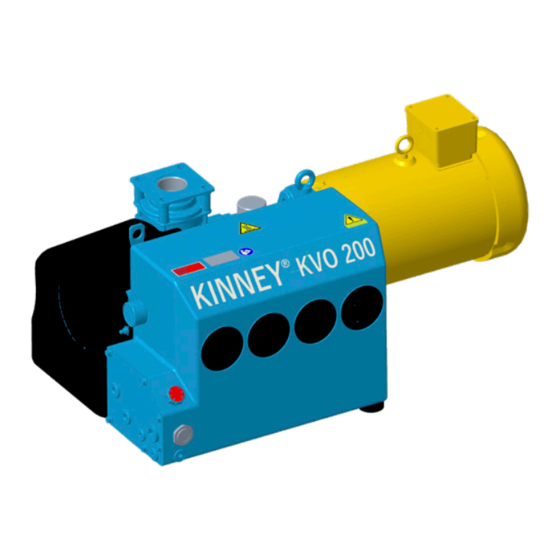
Page 13: Kvo-200 / Kvo-300 Feature Setup
Operation KVO-200 / KVO-300 FEATURE SETUP Vacuum connection Air oil removal device Exhaust air outlet Oil recommendation plate Inlet flange with non-return valve Data plate Cooling air inlet Direction of rotation arrow Cooling air outlet Drive motor Oil filling point Hot surfaces >... -
Page 14: Kvo-400 / Kvo-500 / Kvo-700 / Kvo-900 / Kvo-1100 / Kvo-1300 Feature Setup
Description KVO-400 / KVO-500 / KVO-700 / KVO-900 / KVO-1100 / KVO-1300 FEATURE SETUP Vacuum connection Data plate Exhaust air outlet Rotation direction plate Filter housing Drive motor Cooling air inlet Motor data plate Cooling air outlet Hot surfaces > 70°C Oil filling points Oil remover housing H, H... -
Page 15: Installation
INSTALLATION SAFETY WARNING Use lockout / tagout procedures to disable the electrical energy source before any service or DANGER work is done on the vacuum pumps. Internal and external rotating parts of the pump and driving CAUTION equipment can produce serious physical injuries. -
Page 16: Filling The Pump With Oil
FILLING THE PUMP WITH OIL VACUUM CONNECTION Use oil recommended by Kinney and see the specifications for the quantity of oil required to fill The pumping capacity of the vacuum pump is the pump. Remove the oil fill plug at the top of the reduced if the suction pipe is too narrow and/or long. -
Page 17: Length Of Connection Pipes
When the exhaust air pipe is connected it must be must be installed via a cable fitting to provide checked regularly for impurities. strain relief. Kinney recommends using motor protection switches with delayed switch off, WARNING depending on possible excess current. Temporary excess current may occur when the machine is Do not block the exhaust pipe of the pump. -
Page 18: Operation
OPERATION CHECKING ROTOR WARNING ROTATION DIRECTION Improper use may lead to severe or fatal injuries. Therefore be sure to obey the safety instructions. Operating in the wrong direction of rotation leads to damage to the machine. Use a phase sequence indicator to check the direction of rotation CAUTION (clockwise rotating field). -
Page 19: Maintenance
MAINTENANCE ENSURING OPERATIONAL SAFETY DANGER Danger of death from touching live parts. Before maintenance work disconnect the machine by pressing the main switch or unplugging it and ensure it cannot be turned on again. WARNING Hot surfaces and equipment. During maintenance work there is the danger of getting burnt on hot components and by machine lubricating oil. -
Page 20: Maintenance Interval Schedule
Maintenance SPECIFICATIONS INTERVAL MAINTENANCE TO BE CARRIED OUT Daily Check the oil level Depending on the degree of pollution Clean vacuum pump At least 1 x per month Check the pipes and screws for leaks and ensure their tight fit and if necessary re-seal or re-tighten. Check the terminal box and cable inlet holes for leaks and if necessary re-seal. -
Page 21: Kvo-50 - Kvo-300 Oil Removal
Maintenance OIL DIAGRAMS KVO-50 – 300 Oil Removal Changing: Undo the air oil removers with a ring KVO-50 – KVO-300 Oil Diagram spanner (spanner width 3/4") rotating counter clockwise. Insert new air oil removers with the open lock symbol with the arrow ▼ on the insert and fix turning clockwise (until it clicks into place). -
Page 22: Air Filtering (Models Kvo-50 - Kvo-300)
Maintenance AIR FILTERING WARNING (MODELS KVO-50 – KVO-300) Danger of injury when dealing with compressed air. When blowing through with compressed air, Intake air filter solid particles may be carried along or powder dust swirling around may cause injury to the eyes. The micro filter must be cleaned by rinsing out or Therefore, when cleaning with compressed air purging or replaced more or less often depending... -
Page 23: Coupling
Screw Figure 7-2 – KVO-400 – KVO-1300 air filtering. COUPLING REPLACEMENT PARTS Replacement parts for the KVO Series rotary vane Models KVO-50 – KVO-300 Coupling vacuum pump shown in “Exploded Views and Parts Lists” on page 23. Maintenance kits are The coupling sprocket is subject to wear and must available for the KVO line of pumps. -
Page 24: Troubleshooting
TROUBLESHOOTING Although Kinney vacuum pumps are well-designed and manufactured, problems may occur due to normal wear and the need for readjustment. The following chart lists symptoms that may occur along with probable causes and remedies. SYMPTOM PROBABLE CAUSE REMEDIES Machine is... - Page 25 Troubleshooting SYMPTOM PROBABLE CAUSE REMEDIES Machine gets Ambient or inlet temperatures too high Ensure proper use too hot Cooling air supply is obstructed Check ambient conditions Clean ventilation slots Soiled oil cooler Clean the oil cooler and fan, renew the fan if necessary The lubricating oil is too viscous The oil viscosity must comply with ISO VG 100 as per DIN ISO 3448...
-
Page 26: Part Number Designations
Troubleshooting PART NUMBER DESIGNATIONS Position 4: MOTOR HP EXAMPLE: MODEL KVO100CD-DV Positon 4 Position #: 7.5hp 10hp Position 1 15hp PUMP MODEL NUMBER: 20hp 25hp Position 1 30hp KVO50 40hp KVO75 KVO100 Position 5: KVO150 MOTOR SUPPLIED KVO200 KVO300 Position 5 SIZE KVO400 NEMA... -
Page 27: Exploded Views And Parts Lists
Exploded Views and Parts Lists Exploded Views and Parts Lists KVO-50 / KVO-75 / KVO-100 / KVO-150 SERIES EXPLODED VIEW DRAWING Wearing Parts Seals Repair kits available consisting of V- and D- parts Manual 1867 Rev A p/n 1867... - Page 28 Exploded Views and Parts Lists KVO-50 / KVO-75 / KVO-100 / KVO-150 SERIES PARTS LIST ITEM PART ITEM PART DESCRIPTION DESCRIPTION TYPE TYPE Basic unit Oil-air-cooling / pipework Housing (KVO 50) Oil cooling line Rotor Oil line fitting (KVO 100) Oil line fitting, straight (KVO 100) Blade Fitting, straight (KVO 50/75)
- Page 29 Exploded Views and Parts Lists KVO-200 / KVO-300 SERIES EXPLODED VIEW DRAWING Wearing Parts Seals Repair kits available consisting of V- and D- parts Manual 1867 Rev A p/n 1867...
- Page 30 Exploded Views and Parts Lists KVO-200 / KVO-300 SERIES PARTS LIST ITEM PART ITEM PART DESCRIPTION DESCRIPTION TYPE TYPE Basic unit Threaded plug with seal Housing (KVO 200) Sealing ring Rotor Oil sight glass Blade Pressure gauge ZDM 8 O-Ring Drive O-Ring Coupling driving...
- Page 31 Exploded Views and Parts Lists KVO-400 / KVO-500 / KVO-700 SERIES EXPLODED VIEW DRAWING Wearing Parts Seals Repair kits available consisting of V- and D- parts Manual 1867 Rev A p/n 1867...
- Page 32 Exploded Views and Parts Lists KVO-900 / KVO-1100 / KVO-1300 SERIES PARTS LIST ITEM PART ITEM PART DESCRIPTION DESCRIPTION TYPE TYPE Allen screw (KVO 400) Basic unit 32.6 Housing Allen screw (KVO 500/700) Dowel pin Filter cover Rotor Gasket Blade Oil separator side Oil separator housing cpl.
- Page 33 Exploded Views and Parts Lists ITEM PART ITEM PART DESCRIPTION DESCRIPTION TYPE TYPE Threaded pin Fitting (KVO 500/700) Base Oil line fitting (KVO 500/700) Oil-air-cooling Pipe Fan housing Oil line fitting Fan with coupling cpl. Pipe 58.1 Oil line fitting 58.2 Coupling half, driven Oil passage bolt, double...
- Page 34 Exploded Views and Parts Lists KVO-900 / KVO-1100 / KVO-1300 SERIES EXPLODED VIEW DRAWING Wearing Parts Seals Repair kits available consisting of V- and D- parts Manual 1867 Rev A p/n 1867...
- Page 35 Exploded Views and Parts Lists KVO-900 / KVO-1100 / KVO-1300 SERIES PARTS LIST ITEM PART ITEM PART DESCRIPTION DESCRIPTION TYPE TYPE Allen screw (KVO900) Basic unit 34.6 Housing Allen screw (KVO1100 / 1300) Dowel pin Filter cover Rotor Gasket Blade Oil separator side Oil separator housing cpl.
- Page 36 Exploded Views and Parts Lists ITEM PART ITEM PART DESCRIPTION DESCRIPTION TYPE TYPE 55.4 Coupling rubber Accessories 55.5 Lock ring Pressure gauge ZDM 8 55.6 Spring ring NPT adapter 55.7 Gasket Intermediate flange BSP-NPT Thread adapter Lock plug Gasket 57.1 Sealing ring Labels Lock plug...
-
Page 37: Replacement Kits
Exploded Views and Parts Lists REPLACEMENT KITS AVAILABLE AFTERMARKET PART NUMBER OIL, VANE, KV 100M, QUART 203103 0000 OIL, VANE, KV 100M, 5 GALLON 203105 0000 OIL, VANE, KV 100S, QUART 203106 0000 OIL, VANE, KV 100S, 5 GALLON 203108 0000 OIL, VANE, KV 100FG, QUART 203109 0000 OIL, VANE, KV 100FG, 5 GALLON... -
Page 38: Warranty - Vacuum Products
WARRANTY – VACUUM PRODUCTS Subject to the terms and conditions hereinafter set forth and set forth in General Terms of Sale, Kinney (the Seller) warrants products and parts of its manufacture, when shipped, and its work (including installation and start-up) when performed, will be of good quality and will be free from defects in material and workmanship. -
Page 39: Operating Data Form / Product Registration
NOTES: IMPORTANT All vacuum boosters and vacuum pumps manufactured by Kinney are date coded at time of shipment. In order to assure you of the full benefits of the product warranty, please complete, tear out and return the product registration card. You may also register your product online at www.kinneyvacuum.com or contact... - Page 40 For Service & Repair, Technical Support, or Product Sales contact: Kinney 4840 West Kearney Street Springfield, Missouri USA 65803-8702 O 417.865.8715 800.825.6937 F 417.865.2950 Manual 1867 Rev A p/n 1867 www.kinneyvacuum.com 09/21...
Need help?
Do you have a question about the KVO Series and is the answer not in the manual?
Questions and answers