Table of Contents
Advertisement
Quick Links
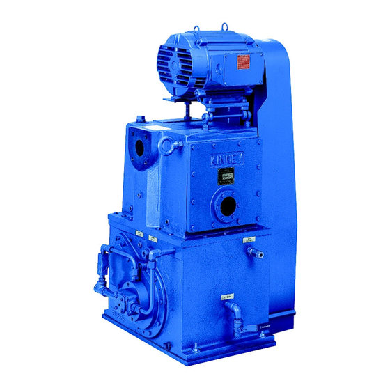
KINNEY
Single Stage, Triplex Rotary Piston Pumps
Models
INSTALLATION
OPERATION
MAINTENANCE
REPAIR
MANUAL
WARNING
DO NOT OPERATE BEFORE
READING MANUAL.
06/2003
KT
®
KT-150 KT-300 KT-500 KT-850
SERIES
™
ADVANCING THE STANDARDS IN VACUUM TECHNOLOGY
4840 West Kearney Street
Springfield, Missouri USA 65803-8702
Tel 417 865-8715 800 825-6937 Fax 417 865-0307
E-mail: kinney@tuthill.com
Manual 1843-1
http://vacuum.tuthill.com
Advertisement
Table of Contents

Related Manuals for KINNEY KT SERIES


Summary of Contents for KINNEY KT SERIES
- Page 1 KT-150 KT-300 KT-500 KT-850 INSTALLATION OPERATION MAINTENANCE REPAIR MANUAL WARNING DO NOT OPERATE BEFORE READING MANUAL. ADVANCING THE STANDARDS IN VACUUM TECHNOLOGY 4840 West Kearney Street Springfield, Missouri USA 65803-8702 Tel 417 865-8715 800 825-6937 Fax 417 865-0307 E-mail: kinney@tuthill.com 06/2003 http://vacuum.tuthill.com...
-
Page 2: Safety Precautions And Warnings
WARNING CAUTION DO NOT VALVE OR RESTRICT PUMP DISCHARGE OPENING. USE OIL MIST ELIMINATOR WHEN OPERATING PUMP. ENSURE ADEQUATE VENTILATION WHEN DISCHARGING INDOORS. DO NOT OPERATE WITHOUT BELT REFER TO MANUAL SAFETY INSTRUCTIONS. GUARD 809762-A000 NOTICE The above safety instruction tags were permanently affixed to your pump prior to shipment. -
Page 3: Table Of Contents
TABLE OF CONTENTS SECTION SAFETY PRECAUTIONS AND WARNINGS INTRODUCTION DESCRIPTION Specifications Description INSTALLATION Installing the Vibramounts Suction Manifolding Proper Venting Discharge Manifolding Cooling Water Filling the Pump with Oil Vacuum Gauges Electrical Connections OPERATION General Prestart Checks Starting The Pump Stopping The Pump Handling Large Quantities of Water Gas Ballast... -
Page 4: Introduction
KINNEY KT vacuum pumps are built to exacting standards and if properly installed and maintained will provide many years of reliable service. We urge you to take time to read and follow every step of these instructions when installing and maintaining your pump. -
Page 5: Specifications
© 2003, Tuthill Corporation INTRODUCTION This manual applies to Kinney Vacuum models KT-150, KT-300, KT-500 and KT-850. You should be thoroughly familiar with these instructions before attempting to install, operate or repair this unit. Consult Tuthill Vacuum & Blower Systems when problems arise that cannot be resolved after reading this manual. Always include pump nameplate information when ordering parts or components. -
Page 6: Description
11. Discharge Valve 12. Gas Ballast Valve 13. Oil Drain 14. Piston Slide 15. Shaft 16. Piston 17. Cam 18. Connection for optional heater 19. Cooling jacket drain 2 of 2 Figure 1. Cross Section of KT Series Vacuum Pump... -
Page 7: Installation
INSTALLATION General Installing the Vibramounts KT pumps are supplied with vibramounts (vibrasprings on the KT-850) which enable them to run quietly and vibration free. The pump can be operated on any floor which will support its weight. The pump must be installed on the vibramounts and flexible connectors fitted in suction, discharge, water and electrical connections. -
Page 8: Suction Manifolding
Key to Figure 3. 1. Oil Mist Eliminator 2. Oil Return Line 3. Gas Ballast Assembly (standard arrangement) Figure 3. Oil Return to the Gas Ballast Valve Suction Manifolding Inlet manifolding should be sized and designed with four objectives in mind: A. -
Page 9: Proper Venting
The installation of a Kinney oil mist eliminator on the discharge is recommended for all applications, (as shown in Figure 4). Oil which collects in the eliminator should be returned to the pump. The optional oil return kit will drain allow oil to back into the separator housing when the pump is operating at low pressure or when the pump is stopped. - Page 10 Key to Figure 4. 1. Discharge connection 2. Relief Valve 3. Top cover gasket 4. Element 5. Oil Drain Connection 6. Optional oil drain line 7. Oil Return connection Figure 4. Oil Mist Eliminator DO NOT ALLOW THE COOLING WATER TO FREEZE IN THE PUMP. Freezing of the cooling water jacket usually results in extensive damage to the pump cylinder which cannot be re- paired.
-
Page 11: Filling The Pump With Oil
Key to Figure 6 1. Waterflow modulating valve (water miser) 2. Temperature sensing bulb 3. Oil Temperature gauge 4. Water Inlet (3/8 NPT) 5. Water outlet (do not restrict or valve) 6. Nipple 7. Reducing bushing Model Water Orifice Size Nipple Reducing Bushing Miser... -
Page 12: Vacuum Gauges
Vacuum Gauges The vacuum gauge(s) to be installed on the pump must be selected to meet the requirements of the particular pump application. Two general types of vacuum gauges are used for the testing of vacuum equipment, total pressure reading, such as thermistor or thermocouple gauges, and partial pressure reading McLeod gauges. The McLeod gauge indicates the partial pressure of permanent gasses. -
Page 13: Starting The Pump
F. Close the vent valve. Handling Large Quantities of Water Use of the gas ballast valve enables Kinney pumps to handle small to moderate amounts of water and other va- pors in the suction gas stream. See the Gas Ballast section below. -
Page 14: Gas Ballast
Factory service is available at Tuthill Vacuum & Blower Systems Factory in Springfield, MO and at our Northeast Service Center in Canton, MA. Authorized independent centers are also available for service of your Kinney pump. Contact us at 1-800-825-6937 for the Authorized Service Center location nearest you. -
Page 15: Changing The Oil
The following factors may cause the pump oil to deteriorate: · Water and solvents will lower viscosity · Solid accumulation will increase viscosity and “feel gritty” · Polymerization and chemical attack on oil will increase viscosity and odor As a “Rule of Thumb” the oil should be changed if: ·... -
Page 16: Stalling
Stalling If the pump stalls at any time, it may be due to loose belts, lack of lubrication caused by failure of the oil circulating pump, badly contaminated oil, coating build up or foreign matter in the pump or oil line strainer (KT-500 and KT-850). If the pump cannot be turned over freely by hand after cooling, there is foreign matter in the pump and the inside of the pump must be cleaned. -
Page 17: Discharging Valves
Key to Fig. 8 1. Capscrew 2. Lift Stop 3. Springs 4. Disc 5. Seat Figure 7. Discharge Valve When leak-checking process chambers, start at the air and gas inlet valves, doors, sight ports, electrical and mechanical feedthroughs, gauge tube fittings, and any other gasketed penetrations and O-ring connections. After a suspected leak has been found, cover it with plastic sealing compound, such as Apiezon Q, and check the equipment performance before sealing the leak permanently. - Page 18 Key to Figure 9A. 1. Shaft seal and bear- ing housing 2. Seal Back-up Ring 3. Shaft seal 4. Bearing back-up ring 5. Ball bearing 6. Locknut 7. Drain plug Figure 8 A. – Shaft Seal and Bearing Housing – KT 150 Key to Figure 9B.
-
Page 19: Shaft-Seal Assembly
The poppet type valve has six flat, washer-like springs which press against a sealing disk. The disk fits against a seal forming a tight seal. The springs are maintained in place by a lift stop and the entire valve is held together by a capscrew. -
Page 20: Disassembly
DISASSEMBLY AND ASSEMBLY Disassembly The following steps are for complete disassembly of the pump, however the pump should be disassembled only to the extent necessary for servicing. Refer to the illustrations and parts list as needed. Note that the open head is the head through which the shaft extends, and closed head is the head on which the oil pump is mounted. -
Page 21: Assembly
CAUTION: If the inlet ports on the piston face the wrong way the piston cannot pump. 6. Carefully clean the removable wall seating shoulder. Insert the beveled ends of the dowel pins into the outside edge of the floating wall. If necessary, use vacuum grease to hold the pins in the holes. Slide the removable wall into the cylinder from the closed head side with the crescent shaped cutout in the wall oriented to fit around the slide-pin. -
Page 22: Replacement Parts
Recommended Oil The oil recommended for KT Pumps in most applications is Kinney KV-100 oil. KV-100 is specially formulated to pro- vide peak lubrication even in arduous conditions, high pumping capacity at low pressures and resist rust and oxida- tion. -
Page 23: Troubleshooting Chart
See Operation General. Foreign Particles in pump. Disassemble pump and clean. 4. Pump vibrates Inlet or outlet connectors not Use Kinney flexible connectors or flexible. more flexible connectors. Vitration mounts incorrect or not Check to ensure that vibration positioned properly. -
Page 24: Parts List & Exploded Views
Figure 10. Final Pump Assembly... - Page 25 Final Pump Assembly KT-150, KT-300, KT-500, KT-850 Refer to Figure 10. Final P ump Assembly Item No. Description KT-150 KT-300 KT-500 KT-850 Pump Motor Belt Guard Motor Sheave Qd Bushing Pump Sheave Qd Bushing V-Belt Spacer Standoff, Beltguard Vibration Mounts Vibration Mounts Vibration Mounts Stud for Vibration Mount...
- Page 26 Main Pump Assembly KT-150, KT-300, KT-500, KT-850 Refer to Figure 11. & 12. Main Pump Assembly Part 1 & Part 2 Item No. Description KT-150 KT-300 KT-500 KT-850 Cylinder Head Subassembly Head, Open End Head, Closed End Housing, Oil Pump Housing, Brg &...
- Page 27 Main Pump Assembly KT-150, KT-300, KT-500, KT-850 cont. Item No. Description KT-150 KT-300 KT-500 KT-850 Nipple Check, Valve Spring Male Elbow Fem Elbow Nipple Ball Valve Check Valve, Swing Angle Valve, G.B., 1/8 Npt Relief Valve Pipe Plug Male Connector, Gas B. U-Tube, Gas B.
- Page 28 Figure 11. - Main Pump Assembly – Part 1...
- Page 29 Figure 12. – Main Pump Assembly Part...
-
Page 30: Warranty Statement
WARRANTY – VACUUM PRODUCTS Subject to the terms and conditions hereinafter set forth and set forth in General Terms of Sale, Tuthill Vacuum & Blower Systems (the seller) warrants products and parts of its manufacture, when shipped, and its work (including installation and start-up) when performed, will be of good quality and will be free from defects in material and workmanship. - Page 31 NOTES IMPORTANT All KINNEY® vacuum pumps manufactured by Tuthill Vacuum & Blower Systems are date coded at time of shipment. In order to assure you of the full benefits of the product warranty, please complete, tear out and return the product registration card below, or you can visit our product registration web page at http://vacuum.tuthill.com/product_registration...
- Page 32 NO POSTAGE NECESSARY IF MAILED IN THE UNITED STATES BUSINESS REPLY MAIL FIRST-CLASS MAIL PERMIT NO. 2912 SPRINGFIELD MO POSTAGE WILL BE PAID BY ADDRESSEE ATTN CUSTOMER SERVICE – VACUUM PRODUCTS TUTHILL VACUUM & BLOWER SYSTEMS PO BOX 2877 SPRINGFIELD MO 65890-2150...
Need help?
Do you have a question about the KT SERIES and is the answer not in the manual?
Questions and answers