Table of Contents
Advertisement
Quick Links
Advertisement
Table of Contents

Related Manuals for KINNEY KLRC40


Summary of Contents for KINNEY KLRC40
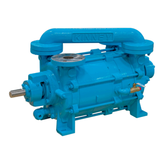
- Page 1 Kinney ® Two-Stage Liquid Ring Vacuum Pump Manual 4804 Rev E p/n 004804 0000 WARNING: Do Not Operate Before Reading Manual KLRC™ OPERATOR’S MANUAL Models KLRC40 KLRC200 KLRC526 KLRC75 KLRC300 KLRC950 KLRC125 KLRC525 800.825.6937 | www.md-kinney.com Original Instructions...
- Page 2 No part of this publication may be reproduced or used in any form by any means - graphic, electronic or mechanical, including photocopying, recording, taping or information storage and retrieval systems - without the written permission of Kinney ® Product information and specifications subject to change.
-
Page 3: Table Of Contents
Table of Contents Table of Contents Introduction .................. 1 Models Covered by this Manual............1 Nameplate Data ..................1 Suitable Applications ................2 Avoid Damage to the Pump ..............2 Theory of Operation ................2 Properties of Sealants ................. 3 Sealant Temperature ................ - Page 4 Table of Contents Cooling Piping for Mechanical Seals ..........11 Manifold Piping ................... 12 Electrical Connections ................ 12 System Components ................12 Inlet Air Ejectors .................. 13 Soft Foot ....................14 Operation ..................15 Starting the Pump ................15 Pre-Start Checks ................. 15 Initial Start-Up ..................
- Page 5 Table of Contents Reassembly ................23 General ....................23 Reassembly Procedure ............... 24 NDE Impeller/Shaft ..............24 NDE Stage ................24 DE Stage .................. 24 DE Shaft Seal and Bearing Housing ........25 NDE Assembly Preparation ............25 Center Housing and NDE Stage ..........25 NDE Shaft Seal and Bearing Housing ........
-
Page 6: Introduction
KLRC model number. Kinney KLRC vacuum pumps are built to exacting standards and, if properly installed and maintained, will provide many years of reliable service. Read... -
Page 7: Suitable Applications
KLRC Series pumps should never be used as Water is normally used as a liquid seal but may be an attaching area for lifting. unsuitable for some pump applications. Consult Kinney before changing to a different liquid in the pump. Manual 4804 Rev E p/n 004804 0000... -
Page 8: Properties Of Sealants
60°F (16°C). that sealants and sealant systems be carefully To calculate pumping capacity (ACFM) or to evaluated. Consult your Kinney sales professional approximate the capacity when using water at or our application engineers to discuss options. -
Page 9: Safety
SAFETY GRAPHIC CONVENTIONS USED IN OTE: Indicates a procedure, practice, or condition that should be followed in THIS MANUAL order for the equipment to function in the manner intended. The following hazard levels are referenced within this manual: SAFETY INSTRUCTION TAG DANGER CAUTION Indicates a hazardous situation that, if not... - Page 10 Safety • Do not restrict the pump discharge in any CAUTION way, or place valves in the discharge line. The vacuum pump is a compressor and will generate Do not operate the pump with oxygen- high pressures without stalling the motor when enriched gas in the suction line, unless the operated at low suction pressures.
-
Page 11: Installation
INSTALLATION GENERAL V-BELT DRIVE Pumps are partially filled with a water-soluble rust Before attempting to tension any V-belt drive, make inhibitor prior to shipment. This solution should be sure the sheaves are properly aligned. Replace drained or flushed from the pump. Drain pump by V-belts in sets and the position the sheaves to removing drain plugs. -
Page 12: Sealant Recovery Systems
Installation SEALANT RECOVERY SYSTEMS ONCE-THROUGH RECOVERY Figure 3-1 on page 7 through Figure 3-4 on The once-through recovery system takes water page 10 illustrate sealant configurations: directly from the water supply through the pump and discharges it directly through a gas/ •... -
Page 13: Partial Sealant Recovery (Psr)
Installation PARTIAL SEALANT RECOVERY Makeup water is added in a quantity necessary to maintain proper sealing water temperature. This (PSR) is the most commonly used arrangement where sealing liquid conservation is required. In the partial recovery arrangement, the The optional system components are described on pump discharges water and gas into a gas/ page 12. -
Page 14: Full Sealant Recovery (Fsr)
Installation FULL SEALANT RECOVERY (FSR) restrictive devices in the sealant line on a full recovery system that does not use a circulation pump, the sealant liquid is induced into the A full sealant recovery system is a closed- pump under pump suction entirely. For sustained loop sealing configuration that employs a heat operation above 400 Torr (533.28 mbar), on rapid exchanger (water- or air-cooled) to maintain proper... - Page 15 Installation Figure 3-4 – Piping Schematic: Full Sealant Recovery System without Circulating Pump See Specifications on page 20 for size of As the pump creates its own vacuum it will draw connections. Figure 3-1 on page 7 through in the required amount of sealant, so that the Figure 3-4 on page 10 show the connection sealant need not be under pressure when pumping locations for suction and discharge gas, sealant...
-
Page 16: Sealant Flow Control
Installation rates shown in Specifications on page 20 are With a partial recovery system an optional sealant on the order of +10% with no sealant recovery flow control valve actuated by sealant discharge system, +25% to -50% with partial sealant recovery temperature may be used to automatically reduce systems. -
Page 17: Manifold Piping
ELECTRICAL CONNECTIONS INLET CHECK VALVE: Used to automatically isolate pump from process chamber when the vacuum Standard electrical motors supplied with Kinney pump is shut down, by blocking the backflow of air Liquid Ring Pumps are three-phase 230/460 and sealant. Valve must be installed in a horizontal volts 60 Hz, across the line operation. -
Page 18: Inlet Air Ejectors
Installation SEALANT SOLENOID VALVE: Used to establish The standard air ejector is cast iron with a series sealant flow (open) when motor is energized, and 300 stainless steel nozzle. All stainless steel return to closed position when motor is de-energized. ejectors are available upon request. -
Page 19: Soft Foot
Installation SOFT FOOT Soft foot is a condition in which one of the pump feet does not sit flat on the base. Soft foot is usually due to irregularities in the surface to which the pump is mounted. When the bolt on the foot gets tightened, a slight distortion occurs that can affect bearing and seal life as well as cause internal contact between parts. -
Page 20: Operation
OPERATION STARTING THE PUMP CAUTION If the pump has been idle for an extended period of Standard pumps with stainless steel time, turn the pump by hand prior to energizing the impellers (designated with material codes F motor to determine that the impeller is free to turn. or C) are suitable for operation with sealant temperatures up to 160°F (71°C). -
Page 21: Initial Start-Up
Operation INITIAL START-UP 5. A liquid level gauge is installed to allow visual monitoring of the sealant level. NOTE: The limitations on what sealant can be used in the 1. Turn on the main power by closing the external liquid ring pump are based on the following fusible disconnect switch or circuit breaker. -
Page 22: Stopping The Pump
Operation A loud rumbling sound is a sign that cavitation is occurring. It is easily suppressed by raising the inlet pressure above the vapor pressure of the sealant at its operating temperature by bleeding air or another comparable gas into the suction if opening the attentuation valve cannot be used or does not bleed in enough air. -
Page 23: Maintenance
The two shaft bearings should be lubricated every mechanical shaft seals that are commonly used 1,500 hours of operation or every two months. A on Kinney liquid ring pumps. The seal faces must high-temperature grease with an extreme-pressure be protected during installation from particles (EP) additive is recommended. -
Page 24: Preparation For Storage
Maintenance PREPARATION FOR STORAGE If the pump is to be idle for an extended period of time, it should be preserved internally to prevent rust if the sealant liquid is water or water-soluble liquids. The pump can be preserved temporarily (2 to 3 months) by adding a water-soluble rust inhibitor into the pump. -
Page 25: Specifications
SPECIFICATIONS KLRC-40 KLRC-75 KLRC-125 KLRC-200 KLRC-300 KLRC-525 KLRC-526 KLRC-950 KLRC-951 Speed 1750 1750 1750 1750 1750 1750 1450 1150 Drive Type Direct Direct Direct Direct Direct Direct Belt Direct Belt Standard Motor 11.4 30.4 74.6 55.9 Sealant Liquid Required (at 60°F w/ no sealant recovery) L/min Sealant Liquid Required (at 60°F w/ partial sealant recovery) -
Page 26: Disassembly
DISASSEMBLY GENERAL 3. Remove bearing housing flange screws and use two in threaded holes to push off bearing housing. KLRC liquid ring pumps incorporate two sets of tie-rods, which fasten either stages or ends 4. Remove the loose elastomer flinger, the shaft of the pump to the center housing. -
Page 27: Shaft Seal
Disassembly OTE: Verify that further disassembly is DE Stage necessary if: 1. Remove the crossover pipe at connecting • The impeller nut and locknut are not secure. flanges (if not already removed). • The impeller has to be replaced or 2. -
Page 28: Reassembly
REASSEMBLY GENERAL use listed thinner to maintain original fluid consistency. • Assembly should proceed without All pans must be clean. Clean off old sealant film interruption until tie-rods for the at housing interfaces and remove with an effective pump are half-tightened to prevent solvent. -
Page 29: Reassembly Procedure
Reassembly REASSEMBLY PROCEDURE 3. Apply sealing compound to the male end of the NDE impeller housing. (For 40 and 75 models with two male ends, check the cross-sectional NDE Impeller/Shaft drawing for correct end.) Install it, aligning the cast-in index marks on top of housing and end 1. -
Page 30: De Shaft Seal And Bearing Housing
If continuing with a complete Crane shaft seal, standard in cast-iron pumps reassembly, skip to NDE Shaft Seal and (Kinney version FA and BA). No spacer is used Bearing Housing on page 26. If only with Flowserve shaft seal, standard in stainless... -
Page 31: Nde Shaft Seal And Bearing Housing
Reassembly 5. Place the NDE end casing/plate assembly Clearance Check and Adjustment on top of the impeller housing with tie-rods entering the bolt holes and align the index If replacement of casings or housings (end, center, marks. Assemble washers and nuts to tie-rods or bearing) occurs during the repair of a KLRC and lightly tighten them. - Page 32 Reassembly KLRC-40 1 ¼” Wide × 1 ½” Deep SLOT(S) CUTOUT(S) through Slot TYP.4 Places KLRC-525 30° 4” Wide × 2” Deep 7” SCH 40 25° Slot TYP.2 Places Pipe 3 ¼” Wide × 2” Deep Slot TYP.2 Places 12” SCH 40 3”...
- Page 33 Reassembly Figure 8-2 – Bearing Driver Tool Manual 4804 Rev E p/n 004804 0000...
- Page 34 Reassembly Figure 8-3 – Foot Alignment Tool Manual 4804 Rev E p/n 004804 0000...
-
Page 35: Troubleshooting
TROUBLESHOOTING Although Kinney vacuum pumps are well designed and manufactured, problems may occur due to normal wear and the need for readjustment. The following chart lists symptoms that may occur along with probable causes and remedies. SYMPTOM PROBABLE CAUSE REMEDIES Seal incorrectly Reinstall seal. - Page 36 Troubleshooting SYMPTOM PROBABLE CAUSE REMEDIES Coupling misaligned Align. Pump not properly Excessive vibration Anchor. anchored See excessive noise Check inlet pressure and gas flow. Excessive back Reduce height of pump discharge. pressure Too much sealant See Table 3-1 on page 11 for proper flow rate. Motor overloaded liquid Misalignment...
- Page 37 Troubleshooting NOTES Manual 4804 Rev E p/n 004804 0000...
-
Page 38: Parts Lists And Assembly Drawings
Parts Lists and Assembly Drawings CROSS-SECTION KLRC-40 AND KLRC-75 Manual 4804 Rev E p/n 004804 0000... -
Page 39: Parts List - Cast Iron 40 And 75 Klrc Assembly
Parts Lists and Assembly Drawings PARTS LIST – CAST IRON 40 AND 75 KLRC ASSEMBLY ITEM ITEM PART DESCRIPTION PART DESCRIPTION 350** End Plate Hex Socket Cap End Casing NDE Screw End Casing DE Tie-Rod Hex Nut End Plate DE Tie-Rod Plain Washer End Plate NDE Bearing Housing Lock Washer... -
Page 40: Cross-Section Klrc-40Cd And Klrc-75Cd (Stainless)
Parts Lists and Assembly Drawings CROSS-SECTION KLRC-40CD AND KLRC-75CD (STAINLESS) Manual 4804 Rev E p/n 004804 0000... -
Page 41: Parts List - Stainless Steel 40 And 75 Klrc Gasketed Assembly
Parts Lists and Assembly Drawings PARTS LIST – STAINLESS STEEL 40 AND 75 KLRC GASKETED ASSEMBLY ITEM ITEM PART DESCRIPTION PART DESCRIPTION 350** End Plate Hex Socket Cap End Casing NDE Screw End Casing DE Tie-Rod Hex Nut End Plate DE Tie-Rod Plain Washer End Plate NDE Bearing Housing Lock Washer... -
Page 42: Cross-Section Klrc-125 To Klrc-525
Parts Lists and Assembly Drawings CROSS-SECTION KLRC-125 TO KLRC-525 Manual 4804 Rev E p/n 004804 0000... -
Page 43: Parts List - Cast Iron 125-525 Klrc Assembly
Parts Lists and Assembly Drawings PARTS LIST – CAST IRON 125-525 KLRC ASSEMBLY ITEM ITEM PART DESCRIPTION PART DESCRIPTION Bearing Housing Hex Head Cap End Casing DE Screw End Casing NDE Bearing Housing Cap Hex Head End Plate DE Cap Screw End Plate NDE 380** End Plate Hex Socket Cap... -
Page 44: Cross-Section Klrc-125 To Klrc-525 (Stainless)
Parts Lists and Assembly Drawings CROSS-SECTION KLRC-125 TO KLRC-525 (STAINLESS) Manual 4804 Rev E p/n 004804 0000... -
Page 45: Parts List - Stainless Steel 125-525 Klrc Gasketed Assembly
Parts Lists and Assembly Drawings PARTS LIST – STAINLESS STEEL 125-525 KLRC GASKETED ASSEMBLY ITEM ITEM PART DESCRIPTION PART DESCRIPTION Bearing Housing Hex Head Cap End Casing DE Screw End Casing NDE Bearing Housing Cap Hex Head End Plate DE Cap Screw End Plate NDE 380**... -
Page 46: Cross-Section Klrc-950
Parts Lists and Assembly Drawings CROSS-SECTION KLRC-950 Detail A 440 410 Manual 4804 Rev E p/n 004804 0000... -
Page 47: Parts List - 950 Klrc Assembly
Parts Lists and Assembly Drawings PARTS LIST – 950 KLRC ASSEMBLY ITEM ITEM PART DESCRIPTION PART DESCRIPTION 360* Hex Socket Cap Screw End Casing DE End Casing NDE 0.375"-16 x 1" End Plate DE Hex Nut, 0.75" End Plate NDE Flat Washer, 0.75"... -
Page 48: Warranty - Vacuum Products
WARRANTY – VACUUM PRODUCTS Subject to the terms and conditions hereinafter set forth and set forth in General Terms of Sale, Kinney (the Seller) warrants products and parts of its manufacture, when shipped, and its work (including installation and start-up) when performed, will be of good quality and will be free from defects in material and workmanship. -
Page 49: Operating Data Form / Product Registration
NOTES: IMPORTANT All vacuum boosters and vacuum pumps manufactured by Kinney are date coded at time of shipment. In order to assure you of the full benefits of the product warranty, please complete, tear out and return the product registration card. You may also register your product online at www.md-kinney.com or contact... - Page 50 For Service & Repair, Technical Support, or Product Sales contact: Kinney 4840 West Kearney Street Springfield, Missouri USA 65803-8702 O 417.865.8715 800.825.6937 F 417.865.2950 Manual 4804 Rev E p/n 004804 0000 www.md-kinney.com 04/22...
Need help?
Do you have a question about the KLRC40 and is the answer not in the manual?
Questions and answers