Table of Contents
Advertisement
Quick Links
Advertisement
Table of Contents

Related Manuals for IFM DI604A


Summary of Contents for IFM DI604A
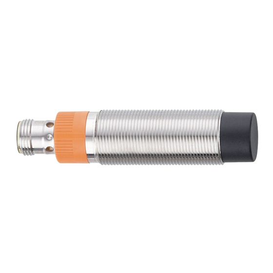
- Page 1 Operating instructions Compact speed monitor M18 DI604A...
-
Page 2: Table Of Contents
DI604A Compact speed monitor M18 Contents Preliminary note ............. -
Page 3: Preliminary Note
Compact speed monitor M18 DI604A 1 Preliminary note You will find instructions, technical data, approvals and further information using the QR code on the unit / packaging or at www.ifm.com. 1.1 Symbols used Requirement Instructions Reaction, result [...] Designation of keys, buttons or indications... -
Page 4: Safety Instructions
DI604A Compact speed monitor M18 2 Safety instructions • The unit described is a subcomponent for integration into a system. – The system architect is responsible for the safety of the system. – The system architect undertakes to perform a risk assessment and to create documentation in accordance with legal and normative requirements to be provided to the operator and user of the system. -
Page 5: Intended Use
Compact speed monitor M18 DI604A 3 Intended use The non-contact unit detects when a set rotational speed value is exceeded or not reached and signals this with a switched output. The unit can be operated in IO-Link mode or in SIO mode (switching output). The pulse output enables external evaluation of the damping pulses in both operating modes. -
Page 6: Function
DI604A Compact speed monitor M18 4 Function The unit has two independently configurable switching channels. About the measuring function: The sensor measures the time between 2 successive transitions from “undamped” to “damped”. The pulse/pause ratio undamped/damped is not relevant, but both the damped and undamped states should be reliably detected. -
Page 7: Window Mode
Compact speed monitor M18 DI604A 4.2 Window mode SP2: Switch-off point SP2-H: Switch-on point SP1: Switch-off point SP1+H: Switch-on point Fig. 3: Normally open = low active If the set speed range is left, the transistor output will signal this as non-conducting. -
Page 8: Two-Point Mode
DI604A Compact speed monitor M18 4.3 Two-point mode SP2: Switch-off point SP1: Switch-on point SP2 SP1 Fig. 5: Normally open = low active If a set rotational speed is not reached, the transistor output will signal this as non-conducting. SP2: Switch-on point... -
Page 9: General Information
Compact speed monitor M18 DI604A 4.4.1 General information The unit has an IO-Link communication interface which requires an IO-Link capable module (IO-Link master). The IO-Link interface allows direct access to the process and diagnostic data and enables setting of the parameters of the unit during operation. -
Page 10: Prescaler
DI604A Compact speed monitor M18 Example: teach offset = 80% / NO (low active) If a teach process is carried out while a motor is running at a nominal rpm of 3,600 pulses/min, the switch point is set to 2,880 pulses/min (80% of the value recorded in teach). In the event of underspeed (< 2,880 pulses/min) the switching output is blocked. -
Page 11: Installation
Compact speed monitor M18 DI604A 5 Installation Fig. 7: Mounting principle Fig. 8: Mounting specifications u Fix the unit using a bracket and secure it by means of the nuts provided so that it cannot work loose. u Adhere to the above mounting specifications to ensure a correct function. -
Page 12: Electrical Connection
DI604A Compact speed monitor M18 6 Electrical connection The unit must be connected by a qualified electrician. u Observe the national and international regulations for the installation of electrical equipment. u Disconnect power. u Connect the unit as follows: 1: L+... -
Page 13: Operating And Display Elements
Compact speed monitor M18 DI604A 7 Operating and display elements Push ring LEDs yellow/green/red 7.1 Push ring (pushbuttons) u To execute a [●] or [▼] command, turn the push ring to the corresponding symbol. Button Function [●] Enter Open menu mode: Parameter setting via the unit keys (Ò / 17). -
Page 14: Parameter Setting
DI604A Compact speed monitor M18 8 Parameter setting Parameter setting can be carried out via the IO-Link interface or via the operating elements on the unit. Parameters can be set before installation or during operation. If you change parameters during operation, this will influence the function of the plant. -
Page 15: Ssc1.X Param. Sp2
Compact speed monitor M18 DI604A 8.1.5 SSC1.x Param. SP2 Switch point 2 (only available in window mode and two-point mode): • 2.1...24,000 pulses/min; factory setting: 2.1 pulses/min 8.1.6 SSC1.x Config. Logic Switch-point logic: • high active (NC) • low active (NO, factory setting) 8.1.7 SSC1.x Config. -
Page 16: Access Locks To The Unit. Local Parameter Setting
DI604A Compact speed monitor M18 • SSC1.1 (factory setting) • SSC1.2 8.1.14 Access locks to the unit. Local parameter setting This lock prevents the settings from being changed via the local operating elements on the unit: • Locked • Unlocked (factory setting) 8.1.15 dSt... -
Page 17: Parameter Setting Via The Unit Keys
Compact speed monitor M18 DI604A 8.2 Parameter setting via the unit keys Unit locking If the LED alternately flashes yellow and green when attempting to set parameters, local parameter setting is disabled. This locking can only be removed using an IO-Link parameter setting software. - Page 18 DI604A Compact speed monitor M18 10 s Operating mode 1 Hz Parameter setting mode Teach SP1 Switch point SP1 1 Hz 1 Hz dSt = 0 s Start-up delay 2 Hz + 1 s >15 s dSt = 1...14 s + 1 s SSC1.1 Config.
- Page 19 Compact speed monitor M18 DI604A u Set the push ring to [●] to teach SP1 with the current damping frequency and save it. w SP1 has been configured. w The LED flashes yellow twice for confirmation; then green with a frequency of 1 Hz.
-
Page 20: Installation/Set-Up Mode
DI604A Compact speed monitor M18 8.2.2 Installation/set-up mode In this mode, the damping state is indicated via the the green LED. The actual damping frequency is indicated up to a frequency of 8 Hz. ü The unit is in the operating mode. -
Page 21: Operation
Compact speed monitor M18 DI604A 9 Operation The operation is maintenance-free. Ensure the following for a correct function: u Keep the sensing face and the clear space free of metal deposits and foreign bodies. u Do not operate devices with high field intensity (e.g. mobile phones) at close range to the speed... -
Page 22: Maintenance, Repair And Disposal
DI604A Compact speed monitor M18 10 Maintenance, repair and disposal The operation of the unit is maintenance-free. Only the manufacturer is allowed to repair the unit. u After use dispose of the device in an environmentally friendly way in accordance with the...
Need help?
Do you have a question about the DI604A and is the answer not in the manual?
Questions and answers