Sign In
Upload
Download
Table of Contents
Contents
Add to my manuals
Delete from my manuals
Share
URL of this page:
HTML Link:
Bookmark this page
Add
Manual will be automatically added to "My Manuals"
Print this page
×
Bookmark added
×
Added to my manuals
Manuals
Brands
IFM Manuals
Measuring Instruments
DD111S
Original installation instructions
IFM DD111S Original Installation Instructions
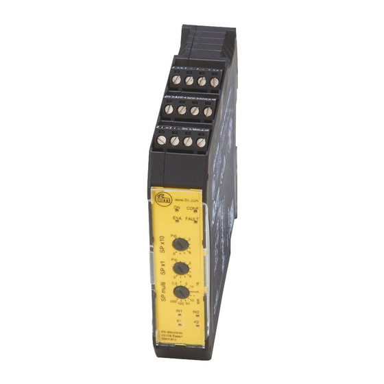
Safety speed monitor
Hide thumbs
1
Table Of Contents
2
3
4
5
6
7
8
9
10
11
12
13
14
15
16
17
18
19
20
21
22
23
24
25
26
27
page
of
27
Go
/
27
Contents
Table of Contents
Bookmarks
Table of Contents
Table of Contents
Preliminary Note
1�1 Symbols Used
1�2 Warnings Used
Safety Instructions
2�1 General Requirements on the Safety-Related Functions
Functions and Features
3�1 General Function Description
3�2 Safe State of the Output Relays
3�3 Switching Function "Overspeed
3�4 Hysteresis
3�5 Initialisation
3�6 Fault Output (Y7)
3�7 Overspeed Output (Y8)
3�8 Feedback Circuit for External Device Monitoring (Y1-Y2)
Installation
4�1 Mechanical Installation of the Device
4�2 Remove the Device
Electrical Connection
5�1 Terminals
5�2 Automatic/Manual Mode Selection
5�2�1 Automatic Mode
5�2�2 Manual Mode
5�3 Enable Input
Indicators and Operating Elements
6�1 Leds
6�2 Switches
Set
7�1 Configuration Position (Factory Setting)
7�2 Setting the Switch Point
7�3 Examples of Switch Point Settings
7�4 Checklist after Installation and Set
Technical Data
8�1 Dd110S
8�2 Dd111S
Advertisement
Quick Links
Download this manual
Original Installation Instructions
Safety speed monitor
UK
DD110S
DD111S
Table of
Contents
Previous
Page
Next
Page
1
2
3
4
5
Advertisement
Table of Contents
Need help?
Do you have a question about the DD111S and is the answer not in the manual?
Ask a question
Questions and answers
Related Manuals for IFM DD111S
Measuring Instruments IFM DI5029 Installation Instructions Manual
Compact speed monitor m18 dc design, io-link, with connector (16 pages)
Measuring Instruments IFM DI5030 Installation Instructions Manual
Compact speed monitor m18 dc design, io-link, with connector (16 pages)
Measuring Instruments IFM DD110S Original Installation Instructions
Safety speed monitor (27 pages)
Measuring Instruments IFM DI604A Operating Instructions Manual
Compact speed monitor m18 (22 pages)
Measuring Instruments IFM SM9x04 Series Operating Instructions Manual
Magnetic-inductive flow meter for ifm efector 300 series (31 pages)
Measuring Instruments IFM SM4x00 Operating Instructions Manual
Magnetic-inductive flow meter (37 pages)
Measuring Instruments IFM SI500A Operating Instructions Manual
Flow monitors (13 pages)
Measuring Instruments IFM SI6600 Operating Instructions Manual
Flow monitor (14 pages)
Measuring Instruments IFM LX Series Operating Instructions Manual
Electronic level sensor (25 pages)
Measuring Instruments IFM SI5011 Operating Instructions Manual
Flow monitors (13 pages)
Measuring Instruments IFM SI5001 Operating Instructions Manual
Flow monitors (13 pages)
Measuring Instruments IFM efector300 VS3000 Operating Instructions Manual
Evaluation system for flow sensors (26 pages)
Measuring Instruments IFM SI0551 Operating Instructions Manual
Flow monitors (13 pages)
Measuring Instruments IFM SU2020 Operating Instructions Manual
Ultrasonic flow meter (54 pages)
Measuring Instruments IFM efector 300 SI5010 Operating Instructions Manual
Flow monitors (13 pages)
Measuring Instruments IFM efector300 SI6000 Operating Instructions Manual
Flow monitors (17 pages)
This manual is also suitable for:
Dd110s
Table of Contents
Print
Rename the bookmark
Delete bookmark?
Delete from my manuals?
Login
Sign In
OR
Sign in with Facebook
Sign in with Google
Upload manual
Upload from disk
Upload from URL


Need help?
Do you have a question about the DD111S and is the answer not in the manual?
Questions and answers